 |
 |
||
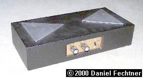
The Southwest Technical Products |
Interior View Showing Circuit Board |
The 144 Theremin
A Revised Version of the Southwest Technical Products Model
142
(Updated December 16, 2002)
Legal Notice
(back to contents)
The information contained in this document is ©2000, 2001, 2002 by Arthur Harrison. Any reproduction of the information contained in this document, electronic or mechanical, shall only be used with Arthur Harrison's permission, and shall acknowledge him as the copyright holder and author.
Use of the information contained in this document for personal or commercial financial gain, such as the manufacture and sale of electronic musical instruments or parts thereof, is prohibited. Unless specifically stated in a written contract, Arthur Harrison grants no licence for the commercial exploitation of the concepts and designs embodied in this document. Refer licensing inquiries to: theremin1@worldnet.att.net.
The information contained in this document may only be reproduced in small quantities when the purpose for its use is the dissemination of information to students or hobbyists, and may not be distributed in any form, electronic or mechanical, for the purposes of any party engaged, directly or indirectly, in commercial enterprises.
Arthur Harrison assumes no liability for any damages, direct, or consequential, which may arise from the dissemination, application, or misapplication of the content contained in this site. The User of the information provided in this site assumes all responsibility for any damages, direct or consequential, which may arise from its use. Arthur Harrison retains the right to alter the content within this site at any time without notice.
The three schematics titled "SOUTHWEST TECHNICAL PRODUCTS CORPORATION THEREMIN (KIT NUMBER 142)" are provided for reference only.
The determination of suitability of the three schematics titled "SOUTHWEST TECHNICAL PRODUCTS CORPORATION THEREMIN (KIT NUMBER 142)" for commercial purposes is the responsibility of the User; the author implies no licence for the utilization of these schematics for commercial purposes.
Acknowledgements
(back to contents)
The author thanks the following persons for their kind assistance in this project:
Barry Eso, Founder of
Theremin Enthusiasts
Club International
Tom Polk, Manufacturer of
Tannerins
Dave Stork
Introduction
(back to contents)
In November, 1967, Popular Electronics magazine published an article by Louis E. Garner, Jr. titled "For that different sound... Music a la Theremin." The article featured a schematic and comprehensive text for constructing a seven-transistor instrument.
A testimony of their popularity, Garner's theremin and its descendant designs are still being constructed to this day. The basic circuit, in fact, is a staple of the Theremin Enthusiasts' Club International (TECI). In response to frequent questions about this circuit, and in tribute to one of the most popular theremin designs ever, I have provided this feature as a source of information to assist those interested in building them.
Southwest Technical Products Corporation (SWTP) was a prominent electronics kit manufacturer that provided parts for many of the Popular Electronics features. (In the original '67 article, SWTP offers a kit of parts, including a printed circuit board, cabinet, and antennas, for $25.00.) The company lasted into the early days of home computing and then vanished as a corporate entity.
In 1974, SWTP issued a new kit with improvements to the original '67 design.
The '74 update confirmed corrections printed in a subsequent Popular
Electronics issue, and also incorporated a few modifications. Among these
were the addition of tuning potentiometers to facilitate nulling, changes
to the pitch oscillators' frequencies to prevent interaction with the volume
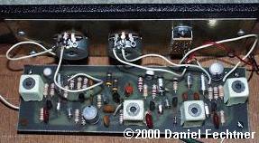
oscillator, and changes to the transistor and inductor types. Photos of a
later model SWTP 142 kit, furnished by correspondent Daniel Fechtner, are
shown below.
|
|
||
The Southwest Technical Products |
Interior View Showing Circuit Board |
The Avalon Theremin
(back to contents)
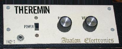
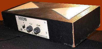
An interesting version of the Southwest Technical Products 142 theremin kit is illustrated in the following photos. The instrument was purchased in the early 1970s, and had become uncalibrated, a problem remedied by readjustment of the variable inductors. The theremin is branded "Avalon Electronics," and has the model number "142-2." There is no indication of a serial number or manufacturing origin, although it is presumed that the parts were obtained from a stock Southwest Technical Products Corporation Model 142 theremin kit, and then assembled by another party, with the "Avalon" nameplate. No prior references to this specific brand of theremin are known at the time of this writing.
A comparison of the schematic for the 142 theremin, in this article, along with comparisons with photographs of assembled 142 theremin kits, revealed that the instrument is electrically identical to the stock unit. The pitch antenna on the Avalon is on the left side, and the volume antenna on the right side, when the instrument is oriented with the controls facing the player. This may indicate that the Avalon 142-2, or at least this particular one, was specifically designed for left-handed players. The Avalon instrument provides the audio output jack on the front panel, instead of the rear panel, as in the Southwest Technical Products Corporation instrument, and has the power switch positioned to the left of the potentiometers, instead of the right.
After calibration with a plastic inductor adjustment tool, I took the opportunity to play the Avalon instrument, and observed that the sensing distances for both the pitch and volume parameters were less than 6", a serious limitation. The volume response was also very non-linear, with most of the change occurring in a one-inch excursion. In comparison, the redesigned version of this instrument, which is the "144" theremin described in this article, offers considerable improvements in these parameters. (Note: Even further improvements are obtained in the newer, "145" theremin design.) I also noticed that the inductor adjustments for the Avalon were extremely critical, with only a very small fraction of a turn causing the instrument to become unplayable. Once the inductors were readjusted, the instrument was restored to its original response, although nominal vibrations from handling the instrument had an adverse affect on the calibration stability, often rendering even the extreme potentiometer positions inadequate.
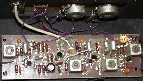
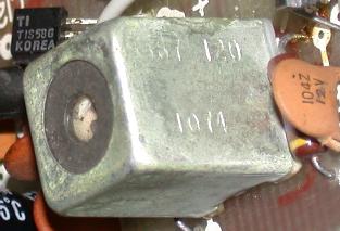
The soldering quality in the Avalon is fairly adequate. Although none of the components appeared defective, all the aluminum electrolytic capacitors were replaced when these photographs were made, since such capacitors tend to deteriorate over very long periods of time. The third photograph is that of the interior, and shows the circuit board. The component locations are silk screened on the printed circuit board, however, the silk screen is aligned very poorly with the component hole locations. Note that the interior photograph of Daniel Fechtner's 142 theremin (above) shows no silk screen, which may indicate that this feature was not consistent among all stock units sold by Southwest Technical Products Corporation. Photograph four clearly shows the part number "387-120" on one of the four inductors. Interestingly, both Daniel Fechtner's 142 theremin and the Avalon theremin are set up for left-handed players.
|
|
|
|
The Southwest Technical Products Corporation's 1974 "Theremin Number 142" kit is represented here in the first set of schematics, redrawn from web resources and photocopies of the original kit instructions. These schematics relate to the later version of the kit, in which rheostats provide the fine-frequency adjustments for the oscillators.
The content in the new schematics is verbatim, except that component designations (R1, R2, etc.) are omitted. To the greatest extent possible, my initial breadboard followed the SWTP schematic and parts recommendations. Observations made from this effort led to modifications in the design, which are shown in the second set of schematics. The revised instrument is designated the "144" theremin.
Improvements implemented in the 144 have produced an instrument which has remarkably good characteristics while maintaining the original design's simplicity. However, I do not recommend this theremin project for the novice, since it exhibits many sensitivities that are greatly affected by the physical placement of components, as well as requirements for test equipment not normally obtainable by the casual experimenter. For those confident in their abilities, assembly drawings have been furnished as a guide for construction. Adherence to the perscribed lay-out is strongly advised. Readers are welcome to contact me with comments.
Schematics for SOUTHWEST TECHNICAL PRODUCTS CORPORATION THEREMIN
(KIT NUMBER 142)
|
 |
 |
Schematics for 144 THEREMIN
|
 |
 |
General Summary of Revisions
(back to contents)
The 2N5087 PNP and 2N5210 NPN bipolar transistors specified in the SWTP parts list are somewhat difficult to obtain, and the Texas Instrument TIS58 N-channel field effect transistor is obsolete. For the 144, I specified types 2N3906, 2N3904, and 2N5484, respectively, as highly appropriate and easily-obtainable substitutes. (Click here for a list of the transistor types specified in various versions of this theremin.)
The SWTP theremins were furnished with one of two types of ferrite-core inductors. Earlier kits had the "loopstick" type mounted on small "L" brackets, and later versions had the miniature, top-adjusted type which are enclosed in rectangular aluminum cans, as illustrated above in the "Avalon Theremin Inductor" photograph.
The sole method for frequency adjustments in the early SWTP version was with the loopstick inductors. Later SWTP versions delegated coarse adjustments to the miniature, enclosed inductors, and fine adjustments to rheostats that were added to two of the oscillator circuits.
In my 144 design, the variable inductors are replaced with fixed-value, J.W. Miller type 4652, phenolic core, 1 millihenry, pie-wound inductors. Coarse frequency adjustments are made with variable capacitors C2 and C22, and fine adjustments are made with potentiometers RV1 and RV2. The new combination of stable, fixed-value inductors and variable capacitors improve the oscillators' frequency stability with temperature change and eliminate the loopsticks or can-type inductors, which are costly and hard to obtain. Note, also, that my 144 design eliminates the variable functions from both the volume processor and the pitch variable oscillator; the nulling adjustments are made only in the pitch reference oscillator and volume oscillator sections.
Inductors, often specified by their inductance value alone, also exhibit other important parameters, such as Q factor, self-resonant frequency, and temperature coefficients. The tendency for arbitrary inductor substitutions often prevent new iterations of the original design from working. The J.W. Miller type 4652 inductors, specified in the 144 design, provide reliable, stable performance.
The 0.01uF polystyrene frequency-determining capacitors in the SWTP version's oscillators are changed to 1000pF in the 144 to facilitate the use of reasonably-sized mica types. Mica capacitors exhibit better temperature stability than polystyrenes, an advantage in this application.
A low-dropout integrated circuit voltage regulator (U1) is added in the new design to reduce parameter drift over battery life. Accordingly, the new circuit's regulated supply is 7.5 volts. The volume section benefits the most from this addition. The DC current consumption for the 144 is less than 10 milliamperes, and it will operate from a single 9-volt alkaline battery.
Frequencies
(back to contents)
Nominal oscillator frequencies are shown in the table below. The expressions' capacitance terms have been expanded for the new circuit. Second-order effects (non-linearities, stray reactances, loading, etc.) are ignored. Frequency variations resulting from potentiometer settings (used by the player to obtain the desired pitch and volume responses) are excluded from the calculations. The values indicated are provided for reference only; actual frequencies may vary considerably due to component tolerances.
 |
Version |
Section |
Notes |
Frequency, Hz |
| SWTP 142 | Volume Oscillator | No antenna, L = 300uH | 304,760 |
| SWTP 142 | Volume Oscillator | No antenna, L = 50uH | 746,500 |
| SWTP 142 | Pitch Reference Oscillator | L = 300uH | 474,280 |
| SWTP 142 | Pitch Reference Oscillator | L = 50uH | 1,139,700 |
144 |
Volume Oscillator | C2 = 25pF | 467,480 |
144 |
Volume Oscillator | C2 = 7pF | 508,640 |
144 |
Pitch Reference Oscillator | C22 = 25pF | 287,910 |
144 |
Pitch Reference Oscillator | C22= 7pF | 296,790 |
Most popular heterodyne theremins utilize frequencies below the AM radio broadcast band to avoid interference from transmitters. Practical values are constrained by the limits of hand-induced capacitance change (only a few picofarads) and the availability of realistically-valued components. The frequencies selected for the 144 are given as practical recommendations, but may have to be altered to prevent interference from specific radio-frequency sources. It should also be noted that the volume and pitch circuits' relative frequencies should not be harmonically related, nor too closely spaced.
Appropriate fixed-capacitor selection and critical adjustment of the variable capacitors is imperative for obtaining appropriate frequencies. A detailed description of the adjustment procedure is contained in the Test and Calibration Procedure section.
Mapping and Sensitivity
(back to contents)
The theremin has two parameters; volume and pitch. The terms "Mapping" and
"Sensitivity" address the theremin's parameter responses to hand positions.
"Mapping" regards the correspondence of a parameter's direction of change
for a given direction of hand motion, (for example, whether the volume increases
or decreases as the hand moves closer to its antenna). "Sensitivity" specifies
the change in a parameter's value for a given change in hand distance, (for
example, the number of octaves the pitch changes for one foot of hand
motion).
Both the SWTP 142 and the 144 are nominally intended to produce an increase
in volume as the hand approaches the volume antenna, and an increase in pitch
as the hand approaches the pitch antenna. Readjustment of oscillator frequencies,
however, may be used to reverse one or both of these relationships. In contrast,
many theremins, especially earlier ones, respond with an increase in volume
as the hand moves away from the volume antenna, whereas a pitch increase
for closer proximity is almost always the rule.
The breadboard for the 144 exhibits a pitch sensitivity of about four octaves
for a span of two feet, and a volume sensitivity of zero to full intensity
for a span of eighteen inches. These sensitivities were observed with battery
operation and no ground connection to the instrument.
While ungrounded operation is extremely useful for portable, headphone operation, a small decrease in sensitivity will result. Also, without a ground connection, some interaction between the volume and pitch control will occur; the pitch will increase slightly as the volume hand is brought close to its antenna. Neither of these conditions, however, pose a major obstacle to the theremin's usefulness as a portable practice instrument. Grounding the instrument will provide complete separation of the volume and pitch functions. Normally, connecting the theremin to external equipment, such as a mains-operated amplifier, will provide a ground connection.
Temperature Sensitivity
(back to contents)
No Vbe temperature compensation is employed in either version's oscillators. Pitch offset stability and sensitivity, therefore, largely depend on the tracking properties of the pitch variable and reference oscillators. Likewise, pitch insensitivity to power supply voltage variations depends on this first-order compensation. This scheme works fairly well as long as thermal gradients are avoided, that is, Q9 and Q10 are kept at constant and equal temperatures.
The volume circuit also exhibits temperature sensitivity related to Q1's temperature-induced Vbe variations. (In addition, the volume circuit has no compensation, since it uses a single oscillator.) For typical temperature variations, changes in the volume oscillator's frequency do not cause severe offsets or changes in volume sensitivity. Although an immediate improvement in temperature stability may be realized with compensated oscillators, I elected to leave the oscillators in their original form in order to retain the design's economy.
Circuit Description, Schematic Page 1: Volume
Oscillator and Volume Processor
(back to contents)
Many comments regarding the SWTPC design regarded difficulty in the volume circuit sections.
The SWTP's slope detector L-C is sufficiently coupled to the volume oscillator so that adjustments in its capacitance or inductance cause the oscillator to shift in frequency just around the L-C's resonance. That is the point where the impedance of the L-C rapidly rises, causing an abrupt change in the oscillator loading, and thus its frequency. As a result, the slope detector is difficult to adjust. In the 144 design, 10kOhm resistor R5 is inserted between the oscillator and slope detector L2-C7 to prevent this undesired coupling. Note that capacitive coupling between inductors L1 and L2 can also degrade performance, so they should be separated by at least two inches.
In the Popular Electronics rendition, volume-response adjustment is even more impaired because the slope detector is fed from the collector of the oscillator transistor, a high impedance point sensitive to loading. In this instance, the slope detector L-C "lumps" into the oscillators resonant circuit, acting as part of the oscillator's frequency-determining network, as opposed to acting as a frequency detector. Here, either a FET source follower or a high value resistance (100kOhm) would be needed to provide adequate isolation. Since the high amplitude of the collector waveform is not required for the detector, the SWTP technique of coupling to the emitter, in conjunction with added resistor R5, combine to provide a better solution.
In the new design, the other method of volume oscillator frequency adjustment is facilitated by varying transistor Q1's bias with potentiometer RV1 via R1. This adjustment, originally implemented as a rheostat-connected potentiometer in the oscillator transistor's emitter circuit, is moved to Q1's base to take advantage of decoupling capacitor C1. An improvement in adjustment linearity results from this change. It should be noted that the potentiometers only facilitate a small change in the instrument's response, and can not compensate for misadjusted variable capacitors (C2 and C22) or incorrectly selected fixed capacitors (C3, C7, C23, and C29).
In the original design, the volume antenna is connected to the volume oscillator, with hand capacitance causing frequency shifts that are processed by the slope detector L-C. As such, certain frequencies emitted by the volume antenna heterodyne with the pitch oscillators, causing undesirable audible products. By connecting the volume antenna to the slope detector tank instead, the radiated energy is constrained to the frequency of the volume oscillator, which remains relatively fixed. (Some frequency change with hand capacitance will occur due to coupling.) The revised scheme works by changing L2-C7's resonance, as opposed to frequency, and unwanted heterodyne products are thus eliminated. An added benefit with this change is that the waveform at the L2-C7 slope detector tank is relatively free of harmonics that are also a potential source of interference.
The SWTP circuit couples the output of the slope tank directly to the DC restoring diode and associated transistor. Parameter variations among different diodes and transistors produce unpredictable loading of the tank, and at the very least, impair its Q. In the 144 , source follower Q2 is incorporated to provide impedance isolation between the tank and detector circuit, eliminating this variable.
Since ample voltage is available at the L2-C7 tank, the germanium DC restoring diode is replaced with a common silicon type (CR1), with an insignificant loss in efficiency. Furthermore, detector-amplifier Q3's gain is set to about 30 with the addition of emitter resistor R10. (In the SWTP design, this stage's gain is controlled by the transistor's widely-ranging hFE, and so is relatively uncontrolled.)
To expound on the above concept, and offer a concise explanation of the volume circuit, the following supplemental description is offered:
| The volume oscillator (Q1 and associated components) provides a non-varying
sinewave to the tuned circuit consisting of L2 and C7. When the resonant
frequency of L2-C7 are equal to the frequency of the oscillator, the amplitude
of the waveform across L2-C7 is greatest. C5 and C6 block the DC biases from
the stages proceeding and following the L2-C7 parallel-resonant circuit,
as it is not desirable to have DC current flowing through L2 and C7.
The volume antenna introduces a second capacitance into the L2-C7 circuit which is the "hand capacitance." As the hand is moved to and from the volume antenna, the changing capacitance causes the resonant frequency of L2-C7 to vary, which also varies the amplitude of the waveform across L2-C7. Since the current present in L2-C7 is very small, a current amplifier consisting of Q2 and associated components is used to prevent the stage following L2-C7 from altering L2-C7's ability to resonate properly. The waveform present at the source terminal of Q2 (top of R8) is essentially the same as the waveform at the top of L2-C7, but it is capable of being loaded by the next stage without becoming distorted. The output of the Q2 stage is coupled to diode CR1 with C9. When the voltage on the right side of C9 becomes negative with respect to ground, CR1 conducts, and the waveform's lowest level becomes reestablished about 0.6v below ground. This process is referred to as "DC restoration." The positive peak of this waveform changes in amplitude according to the amount of hand capacitance. The positive unipolar waveform is fed to amplifier transistor Q3's base, which has capacitor C8 in it's collector to average the pulses into a smoothly-changing DC level. Q3 serves the purpose of both providing gain, to multiply the amount of change at it's base, and also rectification, to prevent C8 from discharging instantaneously when the waveform's slope moves toward zero. Therefore, the signal present at Q3's collector (point "A" in the schematic) is a DC level which changes according to the hand capacitance. The DC level at point "A" controls the channel resistance of Q5. The audio signal from the pitch section of the theremin is present at Q5's source terminal (left side in the schematic). The audio signal appears at Q5's drain terminal (right side) at an amplitude determined by the DC level at Q5's gate. This audio signal is subsequently amplified by the Q6, Q7, and Q8 circuit. In practice, the frequency of the Q1 oscillator must be adjusted so that the amplitude of the waveform at the top of L2-C7 changes in accordance with a function that causes the volume to change properly with hand position. Variable capacitor C2 provides that adjustment, while potentiometer RV1 is used to "fine-tune" the adjustment, as is required for incidental changes in the capacitance caused by the payer's body position, objects near the antenna, and temperature factors that affect the frequency of the oscillator and to a lesser extent, other parts of the circuit. |
Circuit Description, Schematic Page 2: Mixer, Voltage
Controlled Attenuator, and Output Amplifier
(back to contents)
The mixer topology is identical in both versions, except that the DC gain is reduced to 1 in the 144 circuit as opposed to 10 in the original, and the AC gain is reduced from the mixer transistor's hfe value to 10. Also, the low-pass filtering capacitor, C10, is increased to 0.1uF from the SWTP's 1000pF value. C10's value may be altered to modify the instrument's timbre, with useful values ranging from 0.01uF to 1uF. Increasing C10 reduces the amplitude of higher harmonics.
It was observed that the one-FET voltage controlled attenuator, although economical, can not substitute for more elaborate techniques most convenient in integrated-circuit forms. To maximize performance while retaining economy, the new design's FET is arranged in a series configuration, as opposed to the original shunt configuration. As such, Q5 performs a clipping function over much of the attenuation range. This produces significant tonal variation with volume changes, but also improves the linearity and dynamic range of the volume response. (Volume-dependent timbre is considered advantageous in terms of expression, giving the instrument a distinctive character and versatility.) The volume control voltage is applied to Q5's gate via a low-pass filter comprised of R16 and C12. This added filter further attenuates high-frequency heterodyne products produced by the mixer, preventing them from being amplified in the audio stages.
The SWTP design uses a second FET as a source follower for the attenuator stage. This stage is eliminated in the new design, since Q5's drain requires finite loading. The new design's output circuit consists of gain stage Q6, and an output stage consisting of Q7 and Q8. Q7 and Q8 are biased for class AB operation and provide sufficient current gain to drive typical headphones. This configuration, as opposed to a class A output stage, was selected to conserve battery power. Capacitor C16, like C10, reduces the amplitude of higher harmonics, and may be varied or eliminated, as desired.
Useful harmonics may be obtained by lowering the value of R25 and R26 to the point where cross-over distortion occurs, producing a rich tone quality. (Doing so, however, makes the harmonic distribution load dependent.) When varying these resistors, it is advisable to use a current-limited power supply in order to protect the output stage in the event of excessive currents. The cross-over distortion-induced tone quality may be made load independent by replacing the headphones with a fixed-value resistor, and then buffering the output with a subsequent stage.
Circuit Description, Schematic Page 3: Pitch Reference
Oscillator and Pitch Variable Oscillator
(back to contents)
The 144's pitch oscillator topology remains essentially similar to the SWTP design, except that tuning provisions are provided only in the reference section, and the emitter-connected rheostat is replaced with base-connected potentiometer RV2. Resistors R35 and R36 are added to provide additional isolation between the two oscillators' outputs. The SWTP design uses 1000 ohm resistors in each of the oscillators' supply lines. They were found superfluous in terms of isolation, and are thus omitted in the revision. The two pitch oscillator sections should be mounted at opposing ends of the circuit board to minimize their capacitive coupling, to prevent them from injection-locking to each other as they near equal frequencies. In the breadboard, the sections are about six inches apart, with the Q4 mixer section between them.
Circuit Board Assembly
(back to contents)
The assembly drawings illustrate the circuit board as implemented in the 144 prototype. The construction method utilizes perforated board (Vector 169P84WE, cut to a size of 5.6" x 6.8") and push-in terminals (Vector T68). The T68 terminals have a fork to accommodate component leads on the top of the board, and 3-level Wire-Wrap® posts to accommodate Wire-Wrap® connections on the bottom of the board. (NOTE: In the drawings, a simplified representation depict both the component and wire locations on the same plane.)
Use 26 gauge, Kynar® insulated Wire-Wrap® wire. If Wire-Wrap® tooling is not available, 26 gauge, solid, Teflon® insulated wire may be soldered point-to-point instead. Teflon® insulation is highly desirable, since it will not melt with normal soldering temperatures.
To ensure low impedance, flat braid is used for the ground bus, located on the component side of the board. The braid is also used to connect the left lead of capacitor C21 to its associated circuit. The buses are made of the braid material normally used for desoldering.
Click here for large, composite GIFs of the entire circuit board.
Subsection drawings are also provided for one-page printing. "ASSEMBLY DRAWING SECTION IDENTIFICATION, 144 THEREMIN," below, illustrates the relationship of the four sub-section drawings. Click on a section to see its details. The last drawing in this section contains a symbol key.
|
 |
Unit Assembly
(back to contents)
The 144's breadboard was primarily intended for technical evaluation, and was therefore constructed as simply as possible, in an unenclosed fashion. An enclosure may be provided at the user's discretion. If so, care must be taken to minimize the capacitance between the antennas, their wires, and the enclosure. Note that the instrument is configured for right-hand pitch control. The components may be rearranged for left-handed pitch control, if desired.
The components are mounted on a 17" by 11", 3/8"-thick wood base. The circuit board is supported on eight 5/8", 4-40 threaded metal spacers. A 1/16"-thick metal plate is mounted between the circuit board and platform to serve as a ground plane. A 5/8"-27 female threaded fixture may be attached to the underside of the base so that the instrument can be mounted on a microphone stand. The Atlas type AD-11B is suitable for this purpose. (Contact Atlas Sound, 1859 Intertech Drive, Fenton, Missouri 63026 USA, 1-800-876-7337.)
The output jack, potentiometers, and power switch are mounted on a 1/16"-thick right angle aluminum bracket at the front of the base, and the battery is secured to the base with a spring-metal clip.
The volume and pitch antennas are made from 1/16"-thick aluminum, and mounted so that they extend from the left and right edges of the base, respectively, using four sets each of 3/8" long, non-conductive nylon spacers, nylon 6-32 screws, and nylon (or metal) nuts. The spacers are used to separate the antennas from the base, thus reducing stray capacitance. The antennas are connected to their respective circuit board terminals with 16 gauge solid bus wire. Wire attachment to each antenna is made with a number 6 solder lug, secured under one of the antenna support nuts.
22 gauge, stranded, Teflon®-insulated wire is used to interconnect the circuit board, controls, and jack. To avoid unwanted stray capacitances, route these wires in a direct fashion, keeping them away from the antennas, antenna wires, and the area beneath the circuit board.
 |
Parts Table
(back to contents)
Miscellaneous materials, such as screws, nuts, wire, etc. are excluded from
this table. See the Unit Assembly section, above, for recommendations.
Occasionally, distributors delete items from their catalog, in which case,
the Parts List is updated with new sources and part numbers. Please
contact the author if you
have difficulty finding item(s) specified in the Parts Table.
Mouser |
|
Allied |
|
| Harrison Instruments | http://www.harrisoninstruments.com/parts.html |
Newark |
|
Digi-Key |
| ITEM | DESCRIPTION | VALUE | MANUFACTURER |
MANUFACTURER PART |
SUPPLIER | SUPPLIER STOCK NUMBER |
QTY |
| C1,C8, C9,C10, C12,C13, C20,C21, C25,C26, C27,C28 |
CERAMIC CAPACITOR |
0.1 uF +/-10%, X7R, 50 V, RADIAL |
KEMET | CK05BX104K | NEWARK | 87F4662 | 12 |
| C2,C22 (NOTE 1) |
POLYPROPYLENE VARIABLE CAPACITOR |
2 TO 15 pF | SPRAGUE/ GOODMAN |
GYC15000 | DIGI-KEY | SG3006-ND | 2 |
| C3,C7 | MICA CAPACITOR |
100 pF, +/-5%, RADIAL |
CORNELL DUBILIER |
CD10FD101J03 | NEWARK | 15F1360 | 2 |
| C4,C24, C30 |
MICA CAPACITOR |
1000 pF, +/-5%, RADIAL |
CORNELL DUBILIER |
CD15FA102J03 | NEWARK | 15F2610 | 3 |
| C5,C6 | MICA CAPACITOR |
5 pF, +/-5%, RADIAL |
CORNELL DUBILIER |
CD10CD050D03 | NEWARK | 15F1338 | 2 |
| C11,C15, C17,C18 C19 |
TANTALUM CAPACITOR |
10 uF, +/-10%, 20 V, RADIAL |
VISHAY/ SPRAGUE |
199D106X9020CA1 | MOUSER | 74-199D20V10 | 5 |
| C14 | ALUMINUM ELECTROLYTIC CAPACITOR |
220 uF, +/-20%, 10 V, RADIAL |
UNITED CHEMI-CON |
SME10VB221M6X11LL | NEWARK | 95F4530 | 1 |
| C16 | TANTALUM CAPACITOR |
0.47 uF, +/-10%, 35 V |
VISHAY/ SPRAGUE |
199D474X0035AA1 | NEWARK | 17F2049 | 1 |
| C23,C29 (NOTE 2) |
MICA CAPACITOR |
390 pF, +/-5%, RADIAL |
CORNELL DUBILIER |
CD15FD391J03 | NEWARK | 15F1241 | 2 |
| CR1 | DIODE | (USE PART NUMBER) |
CENTRAL SEMICON- DUCTOR |
1N914 | MOUSER | 610-1N914 | 1 |
| L1,L2, L3,L4 |
INDUCTOR, THREE-SECTION, UNIVERSAL "PIE" WOUND |
1 mH, +/-5%, 19 OHM, Q=59 @ 0.25 MHz, SRF=3.7 MHz MINIMUM |
J.W. MILLER | 4652 | HARRISON INSTRUMENTS | 96804-4652 | 4 |
| Q1,Q8, Q9,Q10 |
TRANSISTOR, PNP, TO-92 CASE |
(USE PART NUMBER) |
FAIRCHILD SEMICONDUCTOR |
2N3906 | DIGI-KEY | 2N3906-ND | 4 |
| Q3,Q4 Q6,Q7 |
TRANSISTOR, NPN, TO-92 CASE |
(USE PART NUMBER) |
FAIRCHILD SEMICONDUCTOR |
2N3904 | DIGI-KEY | 2N3904-ND | 4 |
| Q2,Q5 | JUNCTION FIELD EFFECT TRANSISTOR, N-CH., TO-92 CASE |
(USE PART NUMBER) |
CENTRAL SEMICON- DUCTOR |
2N5484 | MOUSER | 610-2N5484 | 2 |
| R1,R12, R16,R30, R31,R35, R36 |
RESISTOR, CARBON FILM |
100K OHM, +/-5%, 1/4 WATT |
XICON | 29SJ250-100K | MOUSER | 291-100K | 7 |
| R2,R18, R32,R37 |
RESISTOR, CARBON FILM |
33K OHM, +/-5%, 1/4 WATT |
XICON | 29SJ250-33K | MOUSER | 291-33K | 4 |
| R3,R33, R38 |
RESISTOR, CARBON FILM |
47K OHM, +/-5%, 1/4 WATT |
XICON | 29SJ250-47K | MOUSER | 291-47K | 3 |
| R4,R25, R26,R34, R39 |
RESISTOR, CARBON FILM |
4700 OHM, +/-5%, 1/4 WATT |
XICON | 29SJ250-4.7K | MOUSER | 291-4.7K | 5 |
| R5,R13, R14 |
RESISTOR, CARBON FILM |
10K OHM, +/-5%, 1/4 WATT |
XICON | 29SJ250-10K | MOUSER | 291-10K | 3 |
| R6,R7 | RESISTOR, CARBON FILM |
4.7M OHM, +/-5%, 1/4 WATT |
XICON | 29SJ250-4.7M | MOUSER | 291-4.7M | 2 |
| R8,R10 | RESISTOR, CARBON FILM |
2200 OHM, +/-5%, 1/4 WATT |
XICON | 29SJ250-2.2K | MOUSER | 291-2.2K | 2 |
| R9 | RESISTOR, CARBON FILM |
68K OHM, +/-5%, 1/4 WATT |
XICON | 29SJ250-68K | MOUSER | 291-68K | 1 |
| R11 | RESISTOR, CARBON FILM |
150K OHM, +/-5%, 1/4 WATT |
XICON | 29SJ250-150K | MOUSER | 291-150K | 1 |
| R15 | RESISTOR, CARBON FILM |
1000 OHM, +/-5%, 1/4 WATT |
XICON | 29SJ250-1.0K | MOUSER | 291-1K | 1 |
| R17 | RESISTOR, CARBON FILM |
120K OHM, +/-5%, 1/4 WATT |
XICON | 29SJ250-120K | MOUSER | 291-120K | 1 |
| R19 | RESISTOR, CARBON FILM |
680 OHM, +/-5%, 1/4 WATT |
XICON | 29SJ250-680 | MOUSER | 291-680 | 1 |
| R20 | RESISTOR, CARBON FILM |
220 OHM, +/-5%, 1/4 WATT |
XICON | 29SJ250-220 | MOUSER | 291-220 | 1 |
| R21 | RESISTOR, METAL FILM |
20.0K OHM +/-1%, 1/4 WATT |
XICON | 271-20K | MOUSER | 271-20K | 1 |
| R22 | RESISTOR, METAL FILM |
3920 OHM +/-1%, 1/4 WATT |
XICON | 271-3.92K | MOUSER | 271-3.92K | 1 |
| R23 | RESISTOR, CARBON FILM |
1M OHM, +/-5%, 1/4 WATT |
XICON | 29SJ250-1.0M | MOUSER | 291-1M | 1 |
| R24,R27 | RESISTOR, CARBON FILM |
22K OHM, +/-5%, 1/4 WATT |
XICON | 29SJ250-22K | MOUSER | 291-22K | 2 |
| R28,R29 | RESISTOR, CARBON FILM |
10 OHM, +/-5%, 1/4 WATT |
XICON | 29SJ250-10 | MOUSER | 291-10 | 2 |
| RV1,RV2 | POTENTIOMETER | 20K OHM, +/-10%, LINEAR TAPER, CONDUCTIVE PLASTIC |
CLAROSTAT | RV4NAYSD203A | NEWARK | 04F8775 | 2 |
| U1 | INTEGRATED CIRCUIT |
(USE PART NUMBER) |
MOTOROLA | LP2951ACN | NEWARK | 01F2166 | 1 |
| . | SOCKET FOR U1 |
8-POSITION, WIRE-WRAP(TM) |
MILLMAX | 123-93-308-41-001 | MOUSER | 575-293308 | 1 |
| . | PERFORATED BOARD |
GLASS-EPOXY, 17" X 8.5" X 0.062" |
VECTOR | 169P84WE | MOUSER | 574-169P84WE | 1 |
| (NOTE 3) | TERMINAL | PRESS-FIT, SOLDER FORK TO WIRE-WRAP® |
VECTOR | T68 | MOUSER | 574-T68/C | 2 |
| . | BRAID, BUS | 0.08" WIDE X 5' LONG |
CHEMTRONICS | 80-3-5 | NEWARK | 95F6236 | 1 |
| . | ANTENNA | ALUMINUM, 8" LONG X 5.5" WIDE X 0.062" THICK |
. | . | . | . | 2 |
| . | KNOB, POTENTIOMETER |
0.848"D, 0.744"H, FOR 0.25"D SHAFT |
ALCO | PKES70B-1/4 | NEWARK | 57F2347 | 2 |
| . | SWITCH | SPDT | C & K | 7101SYZQE | MOUSER | 611-7101-001 | 1 |
(NOTE 4) |
JACK | 1/4" STEREO | SWITCHCRAFT | 112B | MOUSER | 502-112B | 1 |
. |
SPACER, CIRCUIT BOARD SUPPORT |
4-40 THREAD, 0.625" LONG, ALUMINUM |
KEYSTONE | 1808 | MOUSER | 534-1808 | 8 |
(NOTE 5) |
SPACER, ANTENNA SUPPORT |
NUMBER 6, CLEAR HOLE, 0.375" LONG, NYLON |
KEYSTONE | 885 | ALLIED | 839-2231 | 8 |
| (NOTE 6) | BRACKET, CONTROL SUPPORT |
. | . | . | . | . | 1 |
| . | BATTERY, NEDA 1604A |
9 VOLT | EVEREADY | 522 | NEWARK | 48F917 | 1 |
| (NOTE 7) | CLIP, MOUNTING, 9 VOLT BATTERY |
. | KEYSTONE | 71 | . | . | 1 |
| . | CONNECTOR, 9 VOLT BATTERY |
. | KEYSTONE | 72-8 | NEWARK | 16F441 | 1 |
NOTES:
1) The variable capacitor indicated replaces an obsolete type used in the breadboard. A minor lay-out modification will be required for the new capacitor.
Note that the Sprague/Goodman type GYC15000, indicated in the list, has three leads. Two of the leads (the "rotor") are electrically connected, and one or both of these leads is connected to circuit ground. The two rotor terminals may be identified with a continuity tester or ohm meter; they will have a low resistance to the metal tuning screw.
C2's third lead ("stator,") is connected to the collector of Q1, and C22's
third lead ("stator") is connected to the collector of Q9, per the schematics.
The GYC15000 leads may be inserted directly through the board, as opposed
to being soldered to terminals.
2) Item indicated replaces CD10 size capacitors used in breadboard. No lay-out
modification required.
3) Manufacturer part number and supplier stock number is for package of 100
each. 167 each required. This item also available in packages of 1000 each
(Mouser stock number 574-T68/M).
4) Stereo jack indicated to alternatively accommodate stereo headphones.
Minor wiring modification required at jack for stereo output.
5) Supplier stock number is for package of 100 each.
6) See text.
7) Not a distributed item; contact Keystone Electronics, 31-07 20th Road,
Astoria, NY 11105 USA.
Cost Estimate
(back to contents)
To provide an approximate cost as of November 30, 1998, I added up the prices of all the distributor items in the Parts Table, and calculated a total of $123.94 (U.S.). The most expensive items included the perforated board ($19.59), the terminals ($7.76 per hundred), inductors L1 through L4 ($3.69 each), and potentiometers RV1 and RV2 ($8.99 each). Also, the Keystone 885 nylon spacers are sold in minimums of 100 pieces ($12.17 per hundred), although only eight are required.
Items not included in the estimate are: the antennas, the wood base, the control support bracket, and incidental hardware such as screws, nuts, wire, etc. This estimate does not address minimum order requirements that may be imposed by certain distributors, nor shipping costs.
Kynar® is a registered trademark of Elf Atochem North America, Inc.
Teflon® is a registered trademark of E. I. du Pont de Nemours and
Company.
Wire-Wrap® is a registered trademark of Cooper Industries, Inc.
Drawing Index
(back to contents)
SOUTHWEST TECHNICAL PRODUCTS CORPORATION THEREMIN
(KIT NUMBER 142), PAGE 1
SOUTHWEST TECHNICAL PRODUCTS CORPORATION THEREMIN
(KIT NUMBER 142), PAGE 2
SOUTHWEST TECHNICAL PRODUCTS CORPORATION THEREMIN
(KIT NUMBER 142), PAGE 3
144 THEREMIN, PAGE 1
144 THEREMIN, PAGE 2
144 THEREMIN, PAGE 3
ASSEMBLY DRAWING SECTION IDENTIFICATION, 144
THEREMIN
ASSEMBLY DRAWING, 144 THEREMIN
ASSEMBLY DRAWING, 144 THEREMIN (PERFORATIONS
OMITTED)
ASSEMBLY DRAWING, 144 THEREMIN (WITH
COMPONENT VALUES)
ASSEMBLY DRAWING SECTION ONE, 144
THEREMIN
ASSEMBLY DRAWING SECTION TWO, 144
THEREMIN
ASSEMBLY DRAWING SECTION THREE, 144
THEREMIN
ASSEMBLY DRAWING SECTION FOUR, 144
THEREMIN
ASSEMBLY DRAWING SYMBOL KEY
UNIT ASSEMBLY, 144 THEREMIN
PITCH REFERENCE OR PITCH VARIABLE OSCILLATOR
OUTPUT
VOLUME OSCILLATOR OUTPUT
IMPEDANCE BUFFER
Text and drawings ©1998, 1999, 2000, 2001, 2002 by Arthur Harrison
|
THE "144 THEREMIN" |
