Minimum Theremin Kit 101 Assembly Instructions

(Back to "Technical Information")

101 Minimum Theremin Important Safety Precautions


Beginners are encouraged to learn about proper soldering techniques before assembling this kit. Internet instructional videos on the topic are available:

Curious Inventor
Basic Soldering Lesson 1 - "Solder & Flux" (PACE, Incorporated; 8 additional lessons available)

Click here for images of a properly soldered kit.

Click here for the Minimum Theremin Troubleshooting Guide. The troubleshooting guide contains valuable advice that will be helpful to you in your construction. It is highly recommended that you read this guide, before you begin soldering.


You will need:

1. Minimum Theremin Kit

2. Tools (available from an electronics distributor such as Mouser Electronics, http//:www.mouser.com/):

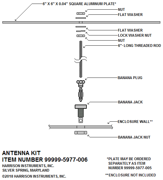
3. Antenna and suitable enclosure (not supplied in kit)


Assembly Instructions:

  1. Unpack the contents of the Minimum Theremin Kit and check that the following items are included:

      Bag Label

      Quantity
    in Bag

      Check

    100 Picofarad Capacitor (C1, C9)

      2


    0.01 Microfarad Capacitor (C2, C4)

      2


    0.1 Microfarad Capacitor (C3)

      1


     10 Microfarad Capacitor (C5, C6, C7, C8)

      4


    1N4148 Diode (CR1, CR3)

     2


    1N4004 Rectifier (CR2)

     1


    270,000 Ohm Resistor (R1, R4, R11)

     3


    27,000 Ohm Resistor (R2, R8, R9, R10)

     4


    22,000 Ohm Resistor (R3, R5, R12)

      3


    100 Ohm Resistor (R6)

      1


    470 Ohm Resistor (R7)

      1


      Bag Label

      Quantity
    in Bag

      Check

    Pitch Zero Trimmer Potentiometer, 10,000 Ohm (RV1)

      1


    CD4069UBE (or equal) Integrated Circuit (U1, U2)

      2


    LP2950ACZ-5.0 Integrated Circuit (VR1)

      1


    9V Battery

      1


    Pitch Zero Control Potentiometer, 1,000 Ohm (Includes: 1 Nut, 1 Washer)

      1


    Output Jack (Includes: 1 Nut, 1 Washer)

      1


    Hookup Wire

      5 Feet


    Switch (Includes: 2 Nuts, 1 Lockwasher, 1 Anti-Rotation Washer)

      1


    Mounting Hardware (Includes: 4 Standoffs, 4 Male-Female Standoffs, 8 Screws)

      1 Set


    Knob (Includes: 1 Set Screw, 1 1/16" Allen Key)

      1 Set


    Battery Connector

      1


    101-PCB Blank PC Board

      1


  2. Mild Oxidation of the solder pads on the PCB may have occurred during storage or transit. These oxides will impede solderability. To remove this oxide, gently rub the pads with an unused pencil eraser. Remove any eraser residue with a clean paper towel.

  3. This is an image of the PCB with the components inserted. Use this as a reference for the following steps.


    101 Minimum Theremin Populated PCB


  4. Attach a pair of Standoffs to each corner of the PCB as illustrated. The Male-Female Standoffs are inserted into the PCB's component side, which is the side with the white printing. The Female Standoffs extend from the PCB's bottom side. The standoffs elevate the board from the work surface to allow the easy insertion of components, and prevent the components from being crushed. The Male-Female Standoffs may be replaced with four of the Machine Screws provided, once the PCB is complete.

    101 Minimum Theremin Standoff Attachment

  5. Form the leads of Resistor R1 with long-nose pliers, as shown:

    101 Minimum Theremin Resistor Lead Preparation

  6. Insert Resistor R1 into the PCB at the location marked "R1." Note that the resistor may be oriented in either direction, however, it is conventional to orient the resistor so that its first band (red band, in the case of R1) is closest to the board's left edge.

  7. Cut off the resistor's excess lead lengths, leaving about 1/16th inch of each lead extending from the board's bottom, as shown in "METHOD 1," below. If you wish, you can bend the resistor's leads against the board's pads, as shown in "METHOD 2," and then cut them. Doing so will help keep the resistor in place when the board is turned over for soldering. (The same choice of these two methods applies to all the other components. The disadvantage of METHOD 2 is that a component will be harder to remove in the event that it has to be replaced.) If you choose METHOD 2, make sure that the bent-over leads do not touch each other or adjacent leads.

    101 Minimum Theremin Resistor Lead Preparation 2

  8. Solder R1 in place. If you used "METHOD 1," above, you can solder one or both of the leads on the top side of the board to keep it in place. Then, turn the board over to solder both leads on the bottom side. Top-soldering the leads is optional, but is useful for keeping the resistor from falling out of the board when METHOD 1 is used. For either method, it is standard practice to always solder the leads on the bottom of the board.

  9. Repeat steps 5 through 8 for the remaining 11 resistors.

  10. Prepare the leads of Capacitors C1, C2, C3, C4, and C9 the same way the resistors were prepared, and solder them in place. Note that these capacitors may be oriented in either direction, however, it is conventional to orient them so that the numerical marking denoting their values are readable. The markings are three digits followed by a letter, as illustrated below. IMPORTANT: These capacitors are very delicate. Do not apply excessive force to their leads. Make sure the capacitors fit easily into the PCB before soldering, because any tension on the leads will cause them to break off the capacitor body while being soldered.

    101 Minimum Theremin Ceramic Capacitors

  11. In the next steps, the two diodes (CR1 and CR3), rectifier (CR2), and three integrated circuits (U1, U2, and VR1) will be installed on the PCB. IMPORTANT: These are "semiconductor" devices that are sensitive to static electricity. Static electricity is a charge that accumulates on your body's surface and on other objects. You can often observe static electricity's effect when you touch a doorknob or other metal object and feel a brief jolt in your hand. While usually harmless to people, it can destroy semiconductors such as those used in this kit. To prevent damage to these devices, discharge any static electricity that may have accumulated on your body by touching a grounded metal object near your workstation, immediately before removing the semiconductors from their conductive foam pad or conductive wrapping. Unwrap the semiconductors at your workstation, and install them in the PCB immediately. Click Here for more information about handling precautions for semiconductors.

  12. Form the leads of Diodes CR1 and CR3 with long-nose pliers as shown:

    101 Minimum Theremin Diode Lead Preparation

  13. Insert Diodes CR1 and CR3 into the PCB at the locations marked "CR1" and "CR3." IMPORTANT: The diodes must be inserted in the correct direction. Make sure that each diode's CATHODE LEAD is inserted into the PCB hole with the SQUARE PAD. As shown in the picture, the cathode lead is the lead designated by the black band on the rectifier's body. Cut off the diodes' excess lead lengths, leaving about 1/16th inch of each lead extending from the board's bottom. Once CR1 and CR3 are correctly inserted, solder them in place.

  14. Form the leads of Rectifier CR2 with long-nose pliers as shown:

    101 Minimum Theremin Rectifier Lead Preparation

  15. Insert Rectifier CR2 into the PCB at the location marked "CR2." IMPORTANT: The rectifier must be inserted in the correct direction. Make sure that the rectifier's CATHODE LEAD is inserted into the PCB hole with the SQUARE PAD. As shown in the picture, the cathode lead is the lead designated by the silver band on the rectifier's body. Cut off the rectifier's excess lead lengths, leaving about 1/16th inch of each lead extending from the board's bottom. Once CR1 is correctly inserted, solder it in place.

  16. Refer to the following picture of Integrated Circuits U1 and U2. Note the notch that designates the end of the device with pins 1 and 14. The ICs may be supplied with their pin rows angled slightly apart. To facilitate their insertion into the PCB, gently form the pin rows so that they are 90 degrees (perpendicular) with relation to the body of the IC. This may be done by carefully pressing each row against a flat surface (such as a tabletop) just enough to bend them perpendicular with the body.

    101 Minimum Theremin IC Lead Identification

  17. Insert ICs U1 and U2 into the PCB at the locations marked "U1 and U2." IMPORTANT: The ICs must be inserted in the correct direction. Make sure that Pin 1 is inserted into the PCB hole with the SQUARE PAD. As shown in the picture, the end of the IC with Pin 1 is designated by the U-shaped notch on the IC's body. Do not confuse the U-shaped notch with the circular recess that may be present at the other end of the IC's package.  Before soldering the ICs into place, verify that they are oriented correctly and that none of the pins have been inadvertently bent, preventing them from going through their hole. Once the ICs are correctly inserted, solder them in place. IMPORTANT: Avoid excessive heat when soldering the ICs.

  18. Form the leads of Voltage Regulator VR1 with long-nose pliers as shown. IMPORTANT: The regulator leads are brittle and will break easily. Form the leads gently, avoiding excessive plier pressure and sharp bends.

    101 Minimum Theremin Voltage Regulator Lead Preparation

  19. Insert Voltage Regulator VR1 into the PCB at the location marked "VR1." IMPORTANT: The regulator must be inserted in the correct direction. Make sure that Pin 1 is inserted into the PCB hole with the SQUARE PAD. As shown in the picture, Pin 1 is the pin on the left when the regulator is oriented with the flat surface facing you and the pins are pointing downward. Cut off the regulator's excess lead lengths, leaving about 1/16th inch of lead extending from the board's bottom. Once VR1 is correctly inserted, solder it in place. IMPORTANT: Avoid excessive heat when soldering the regulator.

  20. Insert the Pitch Zero Trimmer Potentiometer into the PCB at the location marked "RV1." The adjusting screw of the potentiometer is closest to the bottom edge of the board. Once RV1 is correctly inserted, solder it in place, making sure that it is held flat against the board.

  21. Insert Capacitors C5, C6, C7 and C8 into the PCB at their respective locations. Refer to the illustration below to identify their positive (+) leads. IMPORTANT: These four capacitors must be inserted in the correct direction. Make sure that their longer (+) leads are inserted into the PCB holes with the SQUARE PADS. Cut off the capacitors' excess lead lengths, leaving about 1/16th inch of each lead extending from the board's bottom. Solder them in place.

    101 Minimum Theremin Polarized Capacitor

  22. All of the components have now been attached to the PCB. Inspect each soldered connection carefully to ensure that there are no solder bridges between adjacent pads, pads with excess solder, or insufficient solder. Ensure that the ICs, voltage regulator, rectifier, and capacitors C5, 6, 7 and 8 are inserted in the correct direction.

  23. Refer to the figure below. Using Hookup Wire, connect the Switch, Battery Connector, Output Jack, and Pitch Zero Control Potentiometer to the PCB. Note the drawing detail illustrating how the wires are attached to the PCB. Passing the insulated part the wires through the strain relief holes will prevent them from breaking off their solder pads.

    With the exception of the antenna wire, the lengths of the wires connecting the PCB to the off-board components are not critical. For the temporary test arrangement, 4-inch lengths are sufficient. However, plan in advance by making the wires long enough to allow the circuit board to mount to the internal surface of an enclosure (if an enclosure is desired), with the Switch, Output Jack, and Pitch Zero Control Potentiometer mounted through the enclosure's side or sides. If you plan to mount any of the items further away from the PCB, consider this before you commit to specific wire lengths. (The kit is supplied with a five-foot length of wire).


    101 Minimum Theremin Off Board Part Attachment

    Note that the Output Jack has two solder lugs, one called the "tip lug," and the other the "sleeve lug." These must not be interchanged. The lugs can be identified by their different shapes: is the tip and is the sleeve. The sleeve lug may also be identified as the one with "SWITCHCRAFT" stamped into the metal where it extends from the jack. The tip lug is connected to the "LINE OUT" pad on the PCB, and the sleeve lug is connected to the "GROUND" pad on the PCB.

    Attach the Knob to the Pitch Zero Control Potentiometer with the Allen Key provided. The knob has a white index line which indicates the potentiometer's degree of rotation. You may position the index line so that it is approximately in the 7 o'clock position when the potentiometer shaft is fully counterclockwise, and approximately in the 5 o'clock position when the shaft is fully clockwise. Once the potentiometer is mounted to the enclosure, the knob may be repositioned as needed.

    Power will be "ON" when the switch toggle in the "UP" position, as illustrated. The top switch lug is not connected. The power switch wires may be interchanged without affecting operation.

  24. An optional, quick antenna arrangement suited for testing the theremin is illustrated below. It consists of a 6" x 6" square of sheet metal supported on a wood stand. (Many users will want to combine the theremin and all the related components, including the antenna, into one assembly. A typical method is described and illustrated in step 27.)

    The "Materials" chart next to the illustration specifies the Internet distributor McMaster-Carr and their stock numbers for the plate and screw, however, these materials and the wood parts may often be obtained in many local hardware stores. Any type of thin sheet metal and wood may be used.

    The dimensions of the wood pieces are not critical, but the pole should have a relatively small cross-section (for example, 3/4" x 3/4"), and be tall enough (6") to provide adequate capacitive isolation between the plate and the PCB that will be located beneath it.

    Drill a 5/32" hole through the center of the metal square and attach it to the wood stand with the wood screw. One end of the antenna lead wire is stripped and placed between the stand and the metal plate. The other end of the antenna lead wire is connected to the "ANTENNA" pad on the PCB.

    101 Minimum Theremin Antenna Assembly

  25. The Minimum Theremin test arrangement is now ready for evaluation.

    a) Connect a 1/4" phone cord from the theremin's Output Jack to an audio amplifier. Set the amplifier's volume control to nearly minimum ("1" on the volume knob). Connect the 9 Volt Battery to the theremin's Battery Connector. Set the theremin's Power Switch to the "on" position. Note: If you don't have an amplifier, you may use headphones. Most headphones are equipped with a stereo plug, so you will only hear the theremin in one ear. This may be remedied with a suitable "mono source to stereo headphone adapter" such as Radio Shack type 274-360 (note that this adapter is designed for stereo headphones with a 1/4" plug).

    CAUTION:
    Use headphones that have a built-in volume control, and adjust the volume control for a comfortable level. Hearing experts advise against the continuous, extended use of headphones.

    b) Remove any objects, such as wires, tools, or test equipment, within two feet of the Antenna.

    c) Using a small flat-blade screwdriver, set the RV1 Pitch Zero Trimmer Potentiometer on the PCB to its extreme counterclockwise resistance value by turning the slotted adjustment screw at least 15 full counterclockwise rotations. Note that the potentiometer's mechanism has a slip clutch, so it can safely be turned an unlimited number of times in either direction.

    d) Set the Pitch Zero Control to its middle position.

    e) With your hand away from the ANTENNA, slowly turn the RV1 Pitch Zero Trimmer Potentiometer clockwise. No pitch should be heard with RV1 in its extreme counterclockwise position. As RV1 is rotated, a very high pitch will become evident. The pitch will become successively lower with continued rotation, until it stops abruptly. Stop turning RV1 at this point.

    f) Remove the adjustment screwdriver from RV1. Note that the pitch might return; this is a normal condition resulting from the capacitance change that occurs when the screwdriver is removed.

    g) Slowly adjust the Pitch Zero Control just to the point where the pitch stops. This point may occur either slightly clockwise or counterclockwise of its center position.

    h) Starting from a distance of about two feet, move your hand toward the Antenna. Note that the pitch commences at its lowest frequency with your hand about fourteen inches away, increasing as the distance shortens.

  26. An enclosure, if desired, is provided by the user. It can be constructed from any material such as cardboard, wood, plastic, or metal. A metal enclosure will reduce the amount of capacitive coupling between the circuit and antenna. This may result in a more sinusoidal tone and a larger sensing distance than would be obtained with an enclosure made from non-conductive materials.

    Metal enclosures will be electrically connected to the circuit's "ground" in two places; the upper left PCB standoff, and also the output jack's threaded mounting bushing, which is connected to the jack's sleeve lug.

    Note the following guidelines pertaining to the antenna and enclosure:

    a) If a cardboard, wood, or plastic (non-conductive) enclosure is used, do not mount the antenna flush against it, because this may result in too much added capacitance between the antenna and the enclosure. For such enclosures, it is further suggested that the antenna is elevated at least six inches to provide adequate capacitive isolation between the plate and the PCB that will be located beneath it.

    b) If a metal (conductive) enclosure is used, it is suggested that the antenna is likewise elevated at least six inches to prevent too much added capacitance between the antenna and the enclosure.

    c) Keep the Antenna Lead wire short (less than 8 inches) and route it directly to the "ANTENNA" pad on the PCB. Keep the antenna lead as far as practical from other wires or components. If you do not use a plug and socket for your antenna, pass the Antenna Lead wire through the enclosure so that it is perpendicular to the wall. For metal enclosures, take care not to damage the wire's insulation where it passes through the hole. 

    d) While a rod antenna will work in substitution of a plate, using one will cause a considerable alteration in the theremin's response to hand positions, making the tone scale "compressed" into a shorter range of hand distance. This will make the theremin harder to play. If a rod is desired, use a telescoping antenna such as the type found on portable FM radios, extended to about 2 feet.

    e) The antenna and its lead wire have a certain amount of "capacitance" with respect to all nearby objects. As the area of the antenna or the length of the lead wire increases, the value of capacitance increases as well. If the value of capacitance becomes too large, you will not obtain proper theremin operation.

    f) Antennas with alternative shapes and lead wires of different lengths may work, but should not deviate too much from those suggested.

  27. A typical mounting arrangement for the Minimum Theremin is illustrated below. The Table specifies additional items required. The detail drawing shows the hole patterns and recommended hardware arrangements for mounting the Switch, Output Jack, and Pitch Zero Control Potentiometer.

    The square metal plate is attached to a 6-32 threaded rod with two 6-32 hex nuts. The other end of the rod is attached to a banana plug, which plugs into the theremin's antenna jack, allowing easy detachment for transport. The aluminum sheet is supplied as 8" long by 8" wide, and should be trimmed to 6" x 6".

    The PCB is mounted to the wall of the enclosure with the eight Machine Screws and four 3/4" Female Standoffs provided. The 3/4" standoffs may be replaced with shorter ones, but keep at least a 1/4" clearance between the PCB and the enclosure wall. If you want to mount the PCB without screws going through the enclosure wall (as with a thick-walled plywood enclosure), replace the standoffs with hollow number 4 spacers and number 4 wood screws (not supplied in kit). Drill a small hole through the bottom of the box to access the Pitch Zero Trimmer Potentiometer potentiometer.

    The items indicated with an asterisk (*) may be substituted with the Harrison Instruments antenna kit, stock number 99999-5977-006.

    Table
    Item Quantity
    Required
    Manufacturer Part Number Distributor Distributor Stock Number
     6-32 Hex Nut*  2  (Generic)  (Generic)  McMaster-Carr 90257A007
     Aluminum
     Sheet*
     1  (Generic)  (Generic)  McMaster-Carr 89015K166
     6-32
     Threaded  Rod*
     1  (Generic)  (Generic)  McMaster-Carr 95412A373
     Banana Plug*  1  Bel Fuse, Inc.  108-0753-001  Digi-Key
     Electronics
    J149-ND
     Banana Jack*  1  Bel Fuse, Inc.  108-0903-001  Digi-Key
     Electronics
    J152-ND
     Enclosure  1  Polycase  DC47PMBYR  Polycase DC47PMBYR
     Battery Holder  1  Keystone
     Electronics
     Corporation
     79  Digi-Key Electronics 36-79-ND
     2-56 X 3/16"
     Screw
     2  (Generic)  (Generic)  McMaster-Carr 91792A076
     2-56 Hex Nut  2  (Generic)  (Generic)  McMaster-Carr 91841A003

    Minimum Theremin Typical Mounting Arrangement


    2011 01 17

(top)


Text, images, and format ©2006-2019 by Harrison Instruments, Incorporated. No part of this page may be reproduced without express written consent of the copyright holder. Minimum Theremin design used with permission of owner. Specifications may change without notice.

201902020