The 145 Theremin
A New Version of the Model 144 Theremin
Published November 19, 2000
Updated April 25, 2003
Legal Notice
Safety Notices
Acknowledgements
Introduction
Assembly
Schematics
Drawings
Parts Table
Test and Calibration Procedure
Legal Notice
(back to contents)
The information contained in this document is ©2000, 2001, 2002 by Arthur Harrison. Any reproduction of the information contained in this document, electronic or mechanical, shall only be used with Arthur Harrison's permission, and shall acknowledge him as the copyright holder and author.
Use of the information contained in this document for personal or commercial financial gain, such as the manufacture and sale of electronic musical instruments or parts thereof, is prohibited. Unless specifically stated in a written contract, Arthur Harrison grants no licence for the commercial exploitation of the concepts and designs embodied in this document. Refer licensing inquiries to: theremin1@worldnet.att.net.
The information contained in this document may only be reproduced in small quantities when the purpose for its use is the dissemination of information to students or hobbyists, and may not be distributed in any form, electronic or mechanical, for the purposes of any party engaged, directly or indirectly, in commercial enterprises.
Arthur Harrison assumes no liability for any damages, direct, or consequential, which may arise from the dissemination, application, or misapplication of the content contained in this site. The User of the information provided in this site assumes all responsibility for any damages, direct or consequential, which may arise from its use. Arthur Harrison retains the right to alter the content within this site at any time without notice.
Safety Notices
(back to contents)
DANGER: Do not play this instrument at a high volume, especially when using headphones. Use headphones that have a built-in volume control, and adjust the volume control for a comfortable level. Hearing experts advise against the continuous, extended use of headphones.
DANGER: Some of the components used in this construction are "polarized," which means that they will only function properly when inserted into the circuit in the right direction. Always observe component polarities carefully, and double-check the orientation of transistors, diodes, integrated circuits and polarized capacitors before applying power to any circuit. Do not reuse a part which has been subjected to improper insertion.
DANGER: Wear safety glasses and use all appropriate safety equipment when working with tools and materials. Always follow safe shop practices and obey safety rules.
Acknowledgements
(back to contents)
The author thanks Konley Aschenbach, whose assistance in the layout design and construction of the 145 theremin prototype is greatly appreciated.
Introduction
(back to contents)
Since the publication of the type 144 theremin project article in September, 1998, many of them have been successfully constructed. As in the 144, and its forerunner, the Southwest Technical Products model 142, the 145 theremin retains a heterodyne topology similar to that used by Mr. Theremin in his original instruments.
The 145 theremin is similar to the 144 in most respects, excepting the types of oscillators used. The 145 theremin oscillators are differential-pair types that exhibit better temperature stability than the Colpitts oscillators used in the 144. The approximate operating frequencies for the 145 theremin are 270kHz for the volume circuit and 360kHz for the pitch circuit. Compared to the 144, the 145 has improved pitch-arc linearity, with A440 occurring at about 10 inches of hand distance, compared to about 5 inches for the 144. The practical pitch range for the 145 is about 4 1/2 octaves.
Inexpensive silicon rectifiers are used as varactors to provide a volume oscillator tuning range of about 1200Hz and a pitch reference oscillator tuning range of about 700Hz. These frequencies will typically vary within ±10 per-cent among instruments, due to tolerances.
In the new design, oscillator outputs are taken from the resonant L-C pairs, and are low-distortion sine waves. Weak coupling is provided between the two pitch oscillators via C8 and R10 to induce a "lock" condition for zero-beat when the pitch hand is absent. The pitch oscillator levels at the mixer input are unequal, and the mixer output amplitude is significantly reduced in comparison to the 144. This reduction provides a more consistent timbre for varying volume levels, since the amplitude-modulating FET, Q13, is operated in a more linear region. As a result, the 145's timbre has less harmonic content than the 144's. An added filter pole at the mixer's output, R17-C13, provides improved reduction of RF products at the audio output. The audio amplifier has an added AC gain network, R47-C39, in the emitter of the Q14 preamplifier transistor.
As in the 144 theremin, the 145 features the convenience of low current consumption (less than 20 milliamperes) from a single 9-volt battery, enhancing portability as well as safety in construction and use.
I do not recommend this theremin project for the novice, since it exhibits many sensitivities that are greatly affected by the physical placement of components, as well as requirements for test equipment not normally obtainable by the casual experimenter. For those confident in their abilities, assembly drawings have been furnished as a guide for construction. Adherence to the perscribed lay-out is strongly advised.
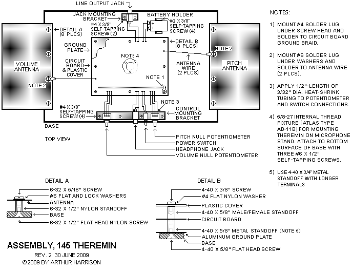
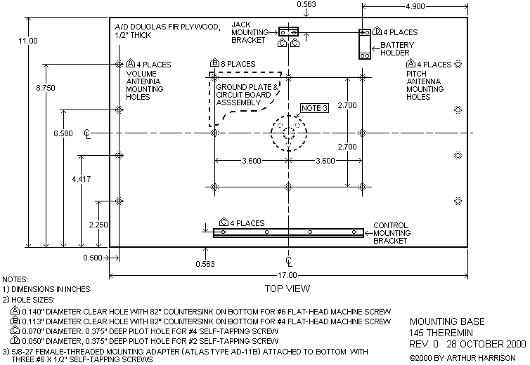
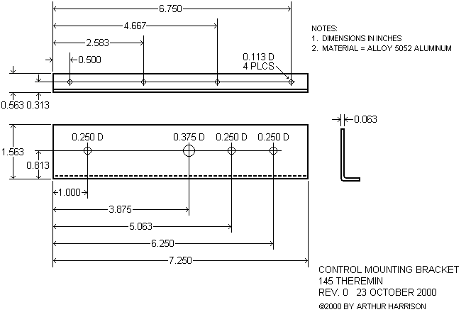
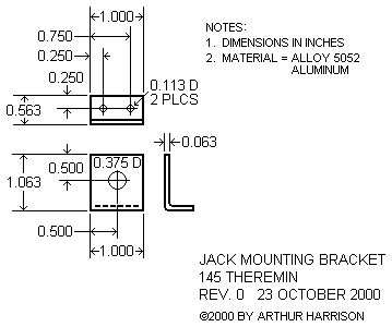
A comprehensive set of mechanical drawings is provided for the 145 theremin. These drawings represent a straightforward implementation of the instrument, constructed on a 17" by 11" plywood base, without an enclosure. This construction method is especially suited for educational demonstrations, since the circuitry is exposed for viewing. Alternatively, the user may enclose the circuit board in a suitable cabinet. If you enclose the theremin, minimize capacitance between the cabinet, antennas, and antenna connections. Refer to the assembly drawing to view an overall lay-out of the instrument. Refer to the mounting base drawing for specific locations of the antennas, brackets, circuit board, and battery holder.
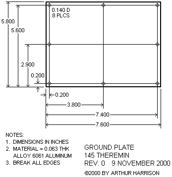
As shown in DETAIL B of the assembly drawing, the circuit board is supported on eight threaded metal standoffs. A metal ground plate is mounted under the circuit board. The plate has eight holes that align with the circuit board's mounting holes. To ensure proper alignment of the plate with the circuit board, it is recommended that the circuit board be used as a template to locate the holes in the plate. This is best done with the circuit board blank, prior to its assembly, so that it can lie flat against the plate. It is also recommended that the blank circuit board be used as a template for hole locations in the wood base. Note that the holes in the plate are a little larger than required for the number 4-40 machine screws used. This provides allowance for tolerances.
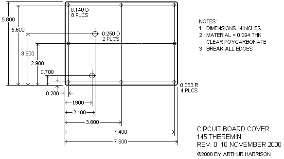
A clear plastic cover is installed above the circuit board. This is recommended to prevent damage to the circuit during transport and demonstration. Again, it is convenient to use the blank circuit board as a template to locate the holes in the cover. The cover is attached to the circuit board with eight male/female-threaded standoffs, screws, and nylon washers, as illustrated in the assembly drawing. Two holes in the cover permit access to the trimming capacitors for calibration.
A 5/8"-27 internal-thread fixture may be attached to the underside of the base so that the instrument can be mounted on a microphone stand. The Atlas Sound type AD-11B is suitable for this purpose. (Atlas Sound, 1859 Intertech Drive, Fenton, Missouri 63026 USA, 1-800-876-7337.)
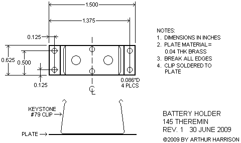
The potentiometers, power switch, and headphone jack are mounted on the control mounting bracket at the front of the base. The line output jack is mounted on the jack mounting bracket at the rear of the base. The battery is secured to the base with a Keystone type 71 spring-metal clip. The clip may be mounted directly to the base with two #2 self-tapping screws, however, the screw heads will prevent the battery from seating completely. An alternative, preferred solution is to solder the clip to a saddle plate with mounting holes outside the battery's footprint, as illustrated in the battery holder drawing. The soldered connections to the potentiometers and the power switch are covered with 1/2"-lengths of heat-shrinkable tubing that provide stress relief for the connections, as well as preventing the potentiometer's flexible terminals from touching each other.
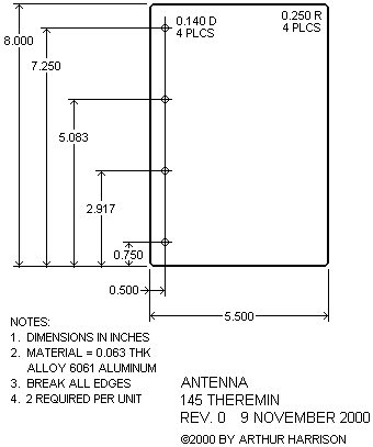
The volume and pitch antennas extend from the left and right edges of the base, respectively. As indicated in DETAIL A of the assembly drawing, the antennas are electrically insulated form the base with 1/2" threaded nylon standoffs. The nylon standoffs are used to separate the antennas from the base, thus reducing stray capacitance. The antennas are connected to their respective circuit board terminals with 16 gauge solid bus wire. Wire attachment is made with a number 6 solder lug, secured by one of the mounting screws at each antenna.
Frequently, users inquire if the plate antennas used for these theremins may be substituted with the traditional form of theremin antennas; the monopole for pitch and loop for volume. Although this may be done, the results will be marginal, since these antenna topologies present less capacitive coupling to the hands, and thus are less efficient. As a result, the theremin's response will occur within smaller arcs of hand movement, closer to the antennas.
Circuit Board
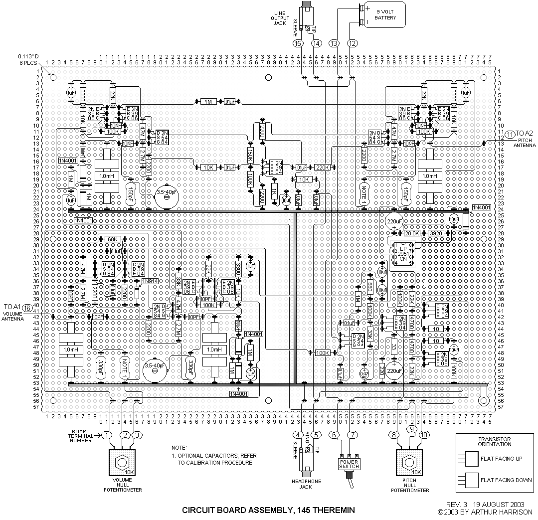
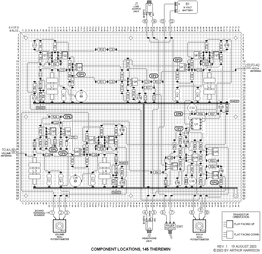
Refer to the circuit board assembly drawing, circuit board component locations drawing, and the circuit board symbol key for component placement and wiring.
The circuit board components are mounted on a sheet of material commonly called "perfboard." The perfboard in the parts list, Vector type 169P84WE, is made of a sturdy glass-epoxy material which resists cracking. Phenolic and paper-epoxy type boards are not recommended, because they are more fragile. The perfboard is furnished with a matrix of 0.042" diameter holes on 0.1" centers. The item listed has 169 columns by 84 rows of holes, and is cut to a size that has 57 by 75 holes, which is 5.8 inches by 7.6 inches.
The board can be cut by deeply scoring along a row of holes with an awl, and then breaking it along the score. If you use this technique, clamp the board and a straight-edge guide securely to a sturdy work surface. Once the board is cut to the proper size, use the circuit board assembly drawing to locate and drill the eight 0.140"-diameter mounting holes.
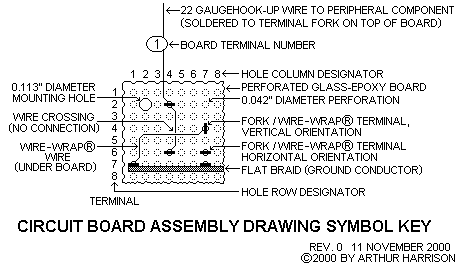
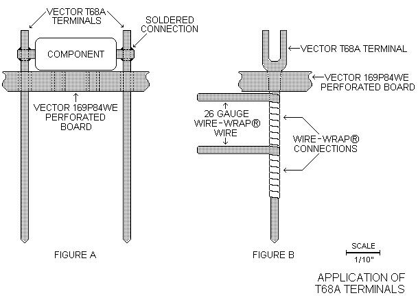
The Vector T68A terminals are pushed into the top side of the perfboard, inserted with long-nosed pliers. They can be quite hard to push in. If so, use a slight alternating clockwise-counterclockwise twisting motion while you push. Make certain that each terminal is securely and squarely seated. The top of the T68A terminal is a two-tined fork, and accepts one or more component leads, or wires that extend from the periphery of the board. The connections to the fork end of the terminal are soldered. The other end is a square cross-section pin, designed to accept a "Wire-Wrap®" connection. The application of the T68A terminal is illustrated below. FIGURE A shows the side view of two terminals with a typical axial-leaded component, such as a resistor, soldered in place. FIGURE B is the front view of a terminal with two levels of wrapped wire. Either one or two levels of wire can be accommodated on each terminal.
Wire-Wrap® is a technique for making rapid, solderless connections. If you do not have Wire-Wrap® tools, the bottom-side connections may be soldered, instead. Before you solder to the pin ends of the terminals, first cut them to a length of 1/4". This will provide space for pliers and the soldering iron tip. The solid conductor, tinned, 26 gauge Kynar® insulated wire specified in the parts list may be either wrapped or soldered. Tefzel® or Teflon® insulated wire may also be used. These insulations are less likely to melt from normal soldering temperatures, but they are harder to strip than Kynar®. A wire with a tinned conductor is desirable, because it solders much more easily than bare copper, which tends to oxidize quickly.
The Vector T68A terminals are quite costly. They are only sold in packages of 1000 for $91.86. Unless the builder routinely requires these terminals for several projects, this will probably be considered an unreasonable expense. To reduce cost, the Vector type T68 terminal, which has a longer tail than the "A" version, may be used. The T68 is less expensive at $49.17 per thousand, and they are also available in packages of 100 for $8.35. If you use the longer, T68 terminal, then the length of the eight threaded metal standoffs used to mount the circuit board should be increased from 5/8" to 3/4" so that the terminals do not touch the ground plane. Note that 250 terminals are required for this project.
A wide braid material, normally used for desoldering, is used for the circuit board's top-side ground "bus." This thick conductor minimizes voltage differences from one ground point to the other. Note that the braid is placed against the edge of the terminals without wrapping or crimping. Make sure that the braid is pushed directly up against the terminal, and inspect each connection carefully to ensure that it is securely bonded after soldering.
22 gauge, stranded, insulated wire is used to interconnect the circuit board, controls, jacks, and battery. All the connections are made to the periphery of the board at the terminals designated "1" through "16" in the circuit board assembly drawing. To avoid stray capacitance, route these wires in a direct fashion, keeping them away from the antennas, antenna wires, and the area beneath the circuit board.
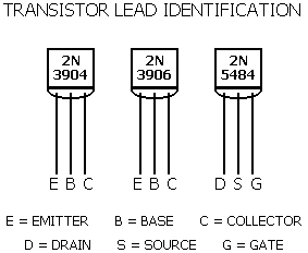
DANGER: It is imperative to observe the correct orientation of the following types of components:
Transistors:
The circuit board assembly drawing distinguishes transistor orientation (flat up or down) with different symbols. Refer to the transistor lead identification drawing for further clarification.
Electrolytic capacitors:
Observe the polarity marking on the electrolytic capacitors and be sure they comply with the circuit board assembly drawing. Polarity indication varies among manufacturers, and even among one manufacturer's lots. Examine each polarized capacitor carefully to determine the correct orientation. DANGER: An incorrectly-inserted electrolytic capacitor can become extremely hot and explode, causing injury, even though the circuit power is limited to the output of a small 9-volt battery!
Diode and rectifiers:
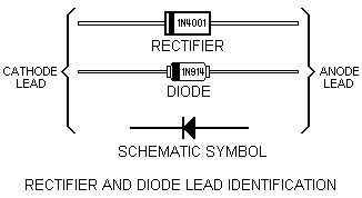
The rectifiers and diode have one end marked with a band, corresponding to the banded ends in the circuit board assembly drawing. The band denotes the "cathode" lead, and corresponds to the bar part of the schematic symbol. The end without a band designates the "anode," which corresponds to the triangular part of the schematic symbol, as shown in the drawing below.
The version of the 1N4001 rectifier specified has an opaque, black plastic case. Versions of the 1N4001 that have a clear glass case should not be used in substitution, because such rectifiers exhibit changes in capacitance with variations in light.
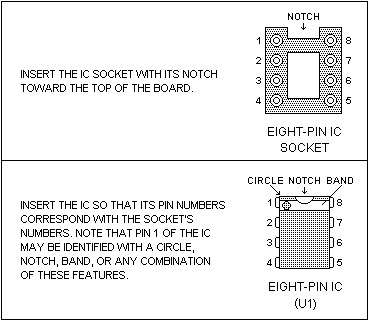
Integrated Circuit:
Determine the location of pin 1 on IC U1's package, and insert it in the socket accordingly.
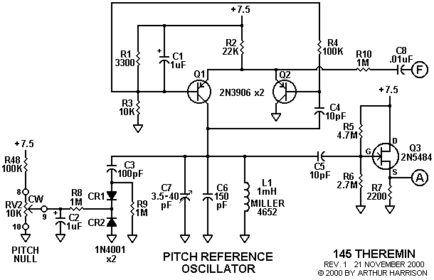
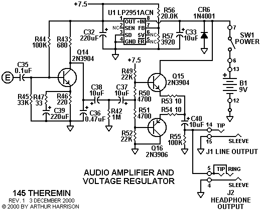
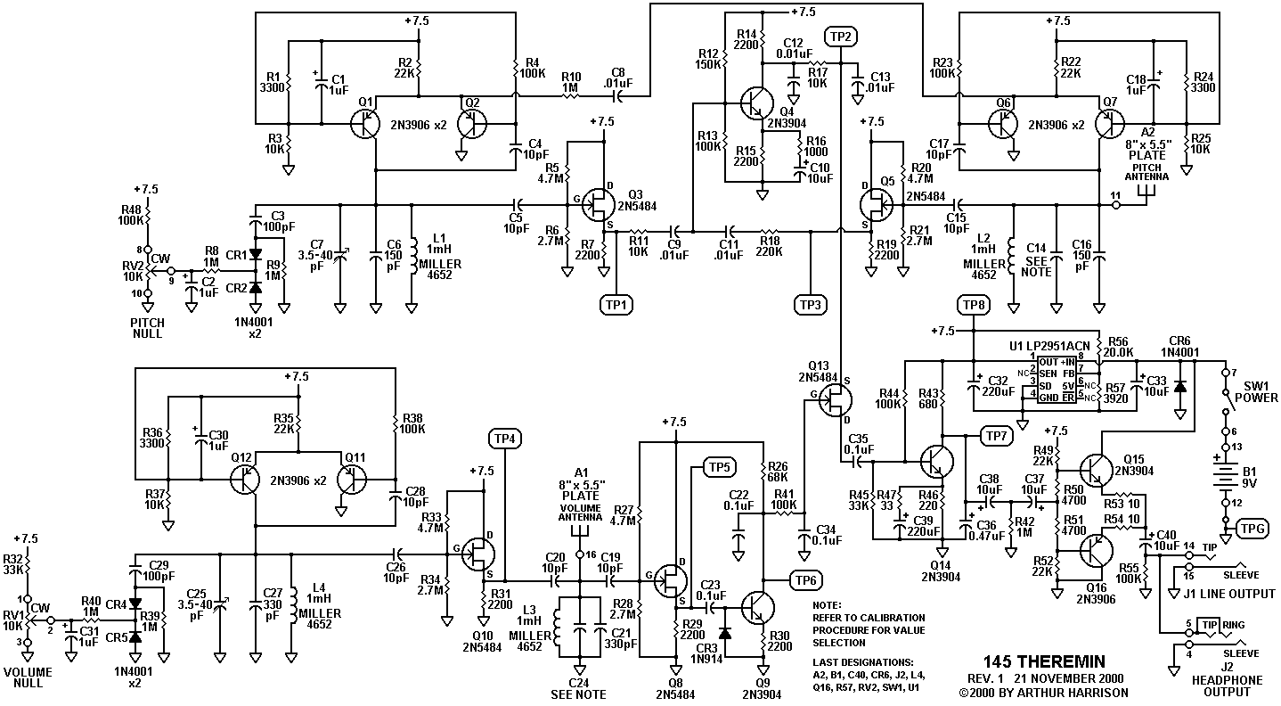
Schematics for 145
Theremin
(back to contents)
The 145 theremin schematic is presented below in six sections. A single-image
schematic can be viewed via the following link:
One-page Schematic
The calibration procedure for capacitor selection, referenced in the Variable
Oscillator and Volume Processor drawings, can be viewed via the following
link: Test and Calibration Procedure
Drawings for 145 Theremin
(back to contents)
| Circuit Board Component Locations |
Parts Table
(back to contents)
Note: The four inductors required for this circuit, J.W. Miller type 4652, are now available from Harrison Instruments. Please contact Harrison Instruments for ordering information.
Mouser |
|
Allied |
|
| Harrison Instruments | http://www.harrisoninstruments.com/parts.html |
Newark |
|
Digi-Key |
|
McMaster-Carr |
| ITEM | DESCRIPTION | VALUE | MANUFACTURER |
MANUFACTURER PART |
SUPPLIER | SUPPLIER STOCK NUMBER |
QTY |
| A1,A2 (NOTE 1) |
ANTENNA | . | . | . | . | . | 2 |
| B1 | BATTERY | 9 VOLT, NEDA 1604 |
EVEREADY | 522 | MOUSER | 525-522 | 1 |
| C1,C2, C18,C30, C31 |
TANTALUM CAPACITOR |
1 uF +/-10%, 35 V, RADIAL |
KEMET | T350A105K035AS | MOUSER | 80-T350A105K035 | 5 |
| C3,C29 | CERAMIC CAPACITOR |
100 pF +/-10%, X7R, 50 V, RADIAL |
MALLORY | CK05BX101K | MOUSER | 539-CK05101K | 2 |
| C8,C9, C11,C12, C13 |
CERAMIC CAPACITOR |
0.01 uF +/-10%, X7R, 50 V, RADIAL |
MALLORY | CK05BX103K | NEWARK | 65F639 | 5 |
| C4,C5, C15,C17, C19,C20, C26,C28 |
CERAMIC CAPACITOR |
10 pF +/-10%, X7R, 50 V, RADIAL |
MALLORY | CK05BX100K | MOUSER | 539-CK05100K | 8 |
| C6,C16 | MICA CAPACITOR |
150 pF +/-5%, RADIAL |
CORNELL DUBILIER |
CD10FD151J03 | NEWARK | 15F1364 | 2 |
| C16 (ALTERNATE PER CALIBRATION PROCEDURE) |
MICA CAPACITOR |
130 pF +/-5%, RADIAL |
CORNELL DUBILIER |
CD15FD131J03 | NEWARK | 15F1229 | 1 |
| C7,C25 |
POLYPROPYLENE VARIABLE CAPACITOR |
3.5 TO 40 pF | SPRAGUE/ GOODMAN |
GYC40000 | DIGI-KEY | SG3008-ND | 2 |
| C10,C33, C37,C38, C40 |
TANTALUM CAPACITOR |
10 uF +/-10%, 20 V, RADIAL |
SPRAGUE | 199D106X9020CA1 | MOUSER | 74-199D20V10 | 5 |
| C14 | MICA CAPACITOR |
SELECTED PER CALIBRATION PROCEDURE |
. | . | . | . | 1 |
| C21,C27 | MICA CAPACITOR |
330 pF +/-5%, RADIAL |
CORNELL DUBILIER |
CD15FD331J03 | NEWARK | 15F1239 | 2 |
| C21 (ALTERNATE PER CALIBRATION PROCEDURE) |
MICA CAPACITOR |
300 pF +/-5%, RADIAL |
CORNELL DUBILIER |
CD15FD301JO3 | ALLIED | 862-4027 | 1 |
| C24 | MICA CAPACITOR |
SELECTED PER CALIBRATION PROCEDURE |
. | . | . | . | 1 |
| C22,C23, C34,C35 |
CERAMIC CAPACITOR |
0.1 uF +/-10%, X7R, 50 V, RADIAL |
MALLORY | CK05BX104K | NEWARK | 65F651 | 4 |
| C32,C39 | ALUMINUM ELECTROLYTIC CAPACITOR |
220 uF +/-20%, 10 V, RADIAL |
XICON | XRL-10V220 | MOUSER | 140-XRL-10V220 | 2 |
| C36 | TANTALUM CAPACITOR |
0.47 uF +/-10%, 35 V |
VISHAY/ SPRAGUE |
199D474X0035AA1 | NEWARK | 17F2049 | 1 |
| CR1,CR2, CR4,CR5, CR6 |
RECTIFIER | (USE PART NUMBER) | RECTRON | 1N4001 | MOUSER | 583-1N4001 | 5 |
| CR3 | DIODE | (USE PART NUMBER) | CENTRAL SEMICON- DUCTOR |
1N914 | MOUSER | 610-1N914 | 1 |
| J1 | JACK | MONO, 1/4" | SWITCHCRAFT | 111 | MOUSER | 502-111 | 1 |
| J2 | JACK | STEREO, 1/4" | SWITCHCRAFT | 112B | MOUSER | 502-112B | 1 |
| L1,L2, L3,L4 |
INDUCTOR, THREE-SECTION, UNIVERSAL "PIE" WOUND |
1 mH +/-5%, 19 OHM, Q=59 @ 0.25 MHz, SRF=3.7 MHz MINIMUM |
J.W. MILLER | 4652 | HARRISON INSTRUMENTS |
96804-4652 | 4 |
| Q1,Q2, Q6,Q7, Q11,Q12, Q16 |
TRANSISTOR | PNP, TO-92 CASE |
FAIRCHILD SEMICONDUCTOR |
2N3906 | DIGI-KEY | 2N3906-ND | 7 |
| Q3,Q5, Q8,Q10, Q13 |
JUNCTION FIELD EFFECT TRANSISTOR | N-CHANNEL, TO-92 CASE | CENTRAL SEMICON- DUCTOR |
2N5484 | MOUSER | 610-2N5484 | 5 |
| Q4,Q9 Q14,Q15 |
TRANSISTOR | NPN, TO-92 CASE |
FAIRCHILD SEMICONDUCTOR |
2N3904 | DIGI-KEY | 2N3904-ND | 4 |
| R1,R24, R36 |
RESISTOR, CARBON FILM |
3300 OHM +/-5%, 1/4 WATT |
XICON | 29SJ250-3.3K | MOUSER | 291-3.3K | 3 |
| R2,R22, R35,R49, R52 |
RESISTOR, CARBON FILM |
22K OHM +/-5%, 1/4 WATT |
XICON | 29SJ250-22K | MOUSER | 291-22K | 5 |
| R3,R11, R17,R25, R37 |
RESISTOR, CARBON FILM |
10K OHM +/-5%, 1/4 WATT |
XICON | 29SJ250-10K | MOUSER | 291-10K | 5 |
| R4,R13, R23,R38, R41,R44, R48,R55 |
RESISTOR, CARBON FILM |
100K OHM +/-5%, 1/4 WATT |
XICON | 29SJ250-100K | MOUSER | 291-100K | 8 |
| R5,R20, R27,R33 |
RESISTOR, CARBON FILM |
4.7M OHM +/-5%, 1/4 WATT |
XICON | 29SJ250-4.7M | MOUSER | 291-4.7M | 4 |
| R6,R21, R28,R34 |
RESISTOR, CARBON FILM |
2.7M OHM +/-5%, 1/4 WATT |
XICON | 29SJ250-2.7M | MOUSER | 291-2.7M | 4 |
| R7,R14, R15,R19, R29,R30, R31 |
RESISTOR, CARBON FILM |
2200 OHM +/-5%, 1/4 WATT |
XICON | 29SJ250-2.2K | MOUSER | 291-2.2K | 7 |
| R8,R9, R10,R39, R40,R42 |
RESISTOR, CARBON FILM |
1M OHM +/-5%, 1/4 WATT |
XICON | 29SJ250-68K | MOUSER | 291-1M | 6 |
| R12 | RESISTOR, CARBON FILM |
150K OHM +/-5%, 1/4 WATT |
XICON | 29SJ250-150K | MOUSER | 291-150K | 1 |
| R16 | RESISTOR, CARBON FILM |
1000 OHM +/-5%, 1/4 WATT |
XICON | 29SJ250-1K | MOUSER | 291-1K | 1 |
| R18 | RESISTOR, CARBON FILM |
220K OHM +/-5%, 1/4 WATT |
XICON | 29SJ250-220K | MOUSER | 291-220K | 1 |
| R26 | RESISTOR, CARBON FILM |
68K OHM +/-5%, 1/4 WATT |
XICON | 29SJ250-68K | MOUSER | 291-68K | 1 |
| R32,R45 | RESISTOR, CARBON FILM |
33K OHM +/-5%, 1/4 WATT |
XICON | 29SJ250-33K | MOUSER | 291-33K | 2 |
| R43 | RESISTOR, CARBON FILM |
680 OHM +/-5%, 1/4 WATT |
XICON | 29SJ250-680 | MOUSER | 291-680 | 1 |
| R46 | RESISTOR, CARBON FILM |
220 OHM +/-5%, 1/4 WATT |
XICON | 29SJ250-220 | MOUSER | 291-220 | 1 |
| R47 | RESISTOR, CARBON FILM |
33 OHM +/-5%, 1/4 WATT |
XICON | 29SJ250-33 | MOUSER | 291-33 | 1 |
| R50,R51 | RESISTOR, CARBON FILM |
4700 OHM +/-5%, 1/4 WATT |
XICON | 29SJ250-4.7K | MOUSER | 291-4.7K | 2 |
| R53,R54 | RESISTOR, CARBON FILM |
10 OHM +/-5%, 1/4 WATT |
XICON | 29SJ250-10 | MOUSER | 291-10 | 2 |
| R56 | RESISTOR, METAL FILM |
20.0K OHM +/-1%, 1/4 WATT |
XICON | 271-20K | MOUSER | 271-20K | 1 |
| R57 | RESISTOR, METAL FILM |
3920 OHM +/-1%, 1/4 WATT |
XICON | 271-3.92K | MOUSER | 271-3.92K | 1 |
| RV1,RV2 (NOTE 7) |
POTENTIOMETER | 10K OHM +/-10%, LINEAR TAPER, CONDUCTIVE PLASTIC |
CLAROSTAT | 308N10K | DIGI-KEY | 308N103-ND | 2 |
| SW1 | SWITCH | SPDT | C & K | 7101SYZQE | MOUSER | 611-7101-001 | 1 |
| U1 | INTEGRATED CIRCUIT |
(USE PART NUMBER) |
ON SEMICONDUCTOR | LP2951ACN | NEWARK | 01F2166 | 1 |
| . | SOCKET FOR U1 |
8-POSITION, WIRE-WRAP® | THOMAS & BETTS/AUGAT | 508AG11F-ES | MOUSER | 506- 508AG11F- ES |
1 |
| . | PERFORATED BOARD |
GLASS-EPOXY, 17" X 8.5" X 0.062" |
VECTOR | 169P84WE | MOUSER | 574-169P84WE | 1 |
| (NOTE 2) | TERMINAL | PRESS-FIT, SOLDER FORK TO WIRE-WRAP® | VECTOR | T68A/M (PKG OF 1000) |
MOUSER | 574-T68A/M (PKG OF 1000) |
1 |
| (ALTERNATE TO ABOVE; AVAILABLE IN PACKAGES OF 100) |
TERMINAL | PRESS-FIT, SOLDER FORK TO WIRE-WRAP® | VECTOR | T68/C (PKG OF 100) |
MOUSER | 574-T68/C | 3 |
| . | BRAID, BUS | 0.08" WIDE X 5' LONG |
CHEMTRONICS | 80-3-5 | NEWARK | 95F6236 | 1 |
| . | KNOB, POTENTIOMETER |
0.848"D, 0.744"H, FOR 0.25"D SHAFT |
ALCO | PKES70B-1/4 | NEWARK | 57F2347 | 2 |
. |
STANDOFF, CIRCUIT BOARD SUPPORT |
4-40 THREAD, 0.625" LONG, ALUMINUM |
KEYSTONE | 1808 | MOUSER | 534-1808 | 8 |
| (ALTERNATE TO ABOVE; FOR USE WITH T68 TERMINALS) |
STANDOFF, CIRCUIT BOARD SUPPORT |
4-40 THREAD, 0.750" LONG, ALUMINUM |
KEYSTONE | 2204 | MOUSER | 534-2204 | 8 |
| . | STANDOFF, PLASTIC COVER SUPPORT |
4-40 THREAD, MALE/FEMALE 0.625" LONG, ALUMINUM . |
KEYSTONE | 8402 | MOUSER | 534-8402 | 8 |
. |
STANDOFF, ANTENNA SUPPORT |
6-32 THREAD, 0.500" LONG, NYLON |
KEYSTONE | 1903C | MOUSER | 534-1903C | 8 |
| (NOTE 1) | BRACKET, CONTROL | . | . | . | . | . | 1 |
| (NOTE 1) | BRACKET, JACK | . | . | . | . | . | 1 |
| (NOTE 1) | PLATE, GROUND | . | . | . | . | . | 1 |
| (NOTE 1) | COVER, PLASTIC | . | . | . | . | . | 1 |
| (NOTE 1) | BASE, PLYWOOD | . | . | . | . | . | 1 |
| . | CLIP, 9 VOLT BATTERY |
. | KEYSTONE | 71 | . | . | 1 |
| (NOTE 1) | MOUNTING PLATE, BATTERY CLIP |
. | . | . | . | . | 1 |
| . | CONNECTOR, 9 VOLT BATTERY |
. | KEYSTONE | 72-8 | NEWARK | 16F441 | 1 |
| . | LUG, SOLDER | NUMBER 4 | KEYSTONE | 7328 | MOUSER | 534-7328 | 1 |
| . | LUG, SOLDER | NUMBER 6 | KEYSTONE | 7312 | MOUSER | 534-7312 | 2 |
| (NOTE 3) | WIRE, HOOK-UP | 22 GAUGE, STRANDED, TEFLON INSULATED, WHITE |
ALPHA | 5855-100-01 (ROLL OF 100') |
MOUSER | 602-5855-100-01 (ROLL OF 100') |
1 |
| (NOTE 4) | WIRE, WIRE-WRAP® | 26 GAUGE, SOLID, KYNAR INSULATED, BLACK |
OK INDUSTRIES | R26BLK-0100 | DIGI-KEY | K386-ND (ROLL OF 100') |
1 |
| (NOTE 5) | WIRE, BUS | 16 GAUGE, TINNED COPPER |
ALPHA | 295-100 (ROLL OF 100') |
MOUSER | 602-295-100 (ROLL OF 100') |
1 |
| (NOTE 6) | TUBING, HEAT-SHRINK | 3/32" DIAMETER, POLYOLEFIN, BLACK |
3M | 05400708436 FP301 3/32 BLACK 48" BK (4' LENGTH) |
MOUSER | 5174-13321 (4' LENGTH) |
1 |
| . | MACHINE SCREW, ANTENNA MOUNTING |
STAINLESS STEEL, PAN HEAD, PHILLIPS, 6-32 X 5/16" |
. | . | MCMASTER- CARR |
91772A145 | 8 |
| . | WASHER, LOCK, ANTENNA MOUNTING |
STAINLESS STEEL, SPLIT-RING, #6, 0.031" THK 0.148" ID 0.250" OD |
. | . | MCMASTER- CARR |
92146A007 | 8 |
| . | WASHER, FLAT, ANTENNA MOUNTING |
STAINLESS STEEL, #6, 0.156"ID, 0.312" OD, MS15795-805 |
. | . | MCMASTER- CARR |
98019A314 | 8 |
| . | MACHINE SCREW, ANTENNA STANDOFF |
NYLON, 82° FLAT HEAD, SLOTTED, 6-32 X 1/2" |
. | . | MCMASTER- CARR |
94605A148 | 8 |
| . | MACHINE SCREW, COVER MOUNTING |
STAINLESS STEEL, PAN HEAD, PHILLIPS, 4-40 X 3/8" |
. | . | MCMASTER- CARR |
91772A108 | 8 |
| . | WASHER, FLAT, COVER MOUNTING |
NYLON, #4, 0.115" ID, 1/4" OD, 0.062" THK |
. | . | MCMASTER- CARR |
90295A045 | 8 |
| . | MACHINE SCREW, CIRCUIT BOARD STANDOFF |
STAINLESS STEEL, 82° FLAT HEAD, PHILlIPS, 4-40 X 5/8" |
. | . | MCMASTER- CARR |
91771A112 | 8 |
| . | SELF-TAPPING SCREW, BRACKET MOUNTING |
STAINLESS STEEL, PAN HEAD, TYPE A, PHILLIPS, #4 X 3/8" |
. | . | MCMASTER- CARR |
92470A108 | 6 |
| . | SELF-TAPPING SCREW, BATTERY HOLDER MOUNTING | STAINLESS STEEL, PAN HEAD, TYPE A, PHILLIPS, #2 X 1/2" |
. | . | MCMASTER- CARR |
92470A098 | 4 |
| . | SELF-TAPPING SCREW, FIXTURE MOUNTING | STAINLESS STEEL, PAN HEAD, TYPE A, PHILLIPS, #6 X 1/2" |
. | . | MCMASTER- CARR |
92470A148 | 3 |
| . | FIXTURE, MICROPHONE STAND MOUNTING |
5/8"-27 INTERNAL THREAD |
ATLAS SOUND | AD-11B | HARRISON INSTRUMENTS |
. | 1 |
Notes:
1) Fabricated item; refer to drawing
2) 250 terminals required.
3) Approximately 10' of hook-up wire required
4) Approximately 40' of Wire-Wrap® wire required
5) Approximately 2' of 16-gauge bus wire required
6) Approximately 4" of heat-shrink tubing required
7) The potentiometers shafts are trimmed to a length of 3/8"
Kynar® is a registered trademark of Elf Atochem North America, Inc.
Teflon® and Tefzel® are registered trademarks of E. I. du Pont de
Nemours and Company.
Wire-Wrap® is a registered trademark of Cooper Industries, Inc.
Text and drawings ©2000, 2001, 2002 by Arthur Harrison
| NOTES FROM OUR 2002 THEREMIN CONFERENCE |
THE "145 THEREMIN" |