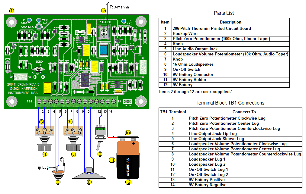
206
Pitch Theremin Printed Circuit Assembly
NOTE:
This page is for "REV. 3" (see "Revisions," below)
Compared to our previous-generation Pitch Theremins,
the 206
Pitch Theremin Printed Circuit Assembly
features reduced
size, improved sensing distance, and improved audio output
drive
capability. A wider pitch-zero control range accommodates greater
variations in antenna capacitance and grounding conditions. Inexpensive
user-supplied materials may be added to the 206 to build a
pitch-only instrument. Electrical connections to the external
components
are easily made with solderless, compression screw terminations.
The 206 is ideal for OEM build-in applications where a reliable,
affordable pitch theremin is required.
Features
* Ideal for OEM
build-in applications, art
and technology
exhibits, and classroom demonstrations
* Operation from a user-supplied
9 volt
battery or 9 to 12 volt power adapter
* Low current consumption for
long battery life
* High-fidelity, pleasing
sine-like output tone with exceptionally low
noise, wide pitch range, and good sensing linearity
* Line output for user-supplied
external amplification
* 8 to 16 ohm loudspeaker output
capable of delivering sufficient volume
for many applications including showrooms, classrooms,
technology
displays, and museum environments
* Accommodates user-supplied
loudspeaker volume and pitch-zero potentiometers
* Stable, low-drift operation
* On-board static suppression
requires no additional components
* Easy calibration with one
on-board adjustment
* Excellent sensing range for
versatility in exhibits and displays
Values are typical,
unless otherwise noted., and specified with
Volume Potentiometer fully clockwise (CW).
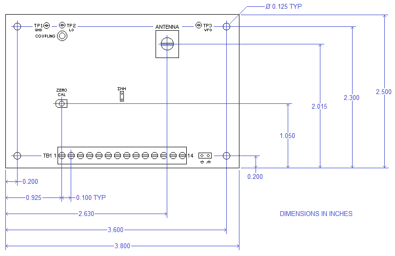
| Dimensions |
3.8" x 2.5" x 0.61"
(9.65cm x 6.35cm x 1.55cm) |
| Weight |
1.2 ounces
(34 Grams) |
| Operating Temperature Range |
+30°F to +90°F
(-1.1°C to +32.2°C) |
| Storage Temperature Range |
-10°F to +120°F
(-23.3°C to +48.8°C) |
| Operating Voltage Range |
7.5 to 9.0 volts DC (8 ohm load)
7.5 to 13.0 volts DC (16 ohm load) |
| Loudspeaker Load Impedance |
8 ohms or greater (See Item 7, Below) |
Operating Current (maximum)
|
75 milliamperes |
Operating Current at Zero Beat
|
6.5 milliamperes |
| Operating Current with INH Jumper Inserted |
4 milliamperes |
Loudspeaker Output Amplitude
|
2.8 volts, P-P
|
Loudspeaker Output Power
|
250 milliwatts (16 ohm load) |
| Loudspeaker Output Roll-Up Frequency (-3dB) |
60 hertz |
| Loudspeaker Output Roll-Off Frequency (-3dB) |
1550 hertz |
Pitch Response to Hand Position
(with Circuit Board in Grounded Metal Enclosure
and Using Recommended Antenna) |
View Graph |
Line Output Amplitude
(10k ohm Load, 440 Hertz)
|
1.0 volt, P-P
|
| Line Output Impedance |
220 ohms |
Line Output Noise at Zero Beat
(Bandwidth = 20Hz to 20kHz)
|
2 millivolts, P-P
|
| Line Output Signal to Noise Ratio |
48 dB |
Local Oscillator Frequency
|
455 ±2 kilohertz
|
| Total Recommended Antenna Capacitance (typical) |
10 picofarads |
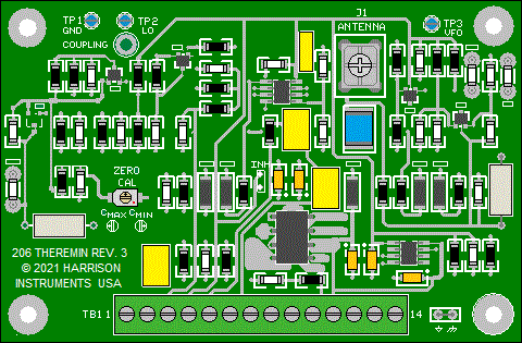
| Test Points |
TP1: ground
TP2: local oscillator waveform
TP3: variable frequency oscillator waveform |
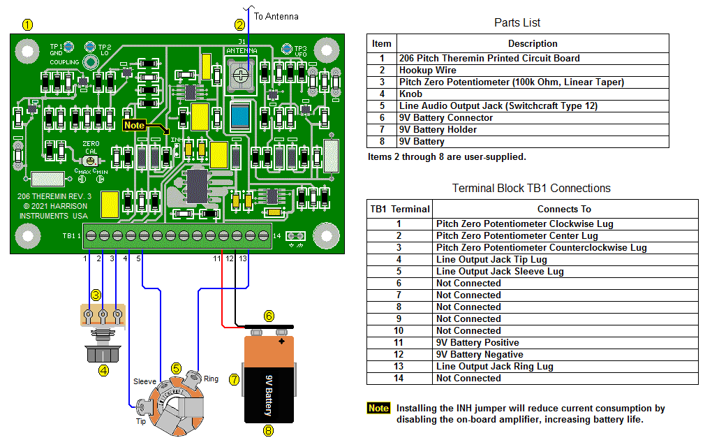
| TB1 Terminal Block |
Wire Range: 24 AWG to 16 AWG (0.5mm
to 1.27mm)
Strip Length: 0.19" to 0.23" (5mm to 6mm)
Recommended Torque: 1.7lb-in (0.19N-m) |
| ANTENNA Terminal |
Wire Range: 22 AWG to 14 AWG (0.64mm
to 1.6mm)
Strip Length: 0.19" to 0.25" (4.8mm to 6.35mm)
Recommended Torque: 2.5lb-in (0.28N-m) |
Revisions
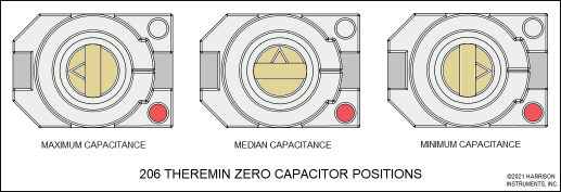
- Revision 3 ("REV. 3") has a new
type of ZERO CAL tuning capacitor. The location of the adjustment screw
has remained the same as in revision 2. Adjustment of the ZERO CAL capacitor
requires a tool, available from Knowles Voltronics, their part number
TT-400, or from Harrison Instruments (please contact us.) Alternatively, a slot jewelers' screwdriver with a 0.16mm x 0.8mm blade, such as Wiha type 26008, may be used. The new ZERO CAL capacitor can only be adjusted from the top-side of the board.
- Revision
3 has relocated the "COUPLING" pad. It is now located below test point
2 ("TP2"), and has a lager diameter to accommodate a 2-56 screw or 2-56 diameter threaded
rod. The effectiveness of the coupling has been improved significantly, to
more-easily obtain variations in the tone harmonics with relatively
short coupling extensions.
Dimensions
* Suggested Sources
Application
Instructions
- The 206
Theremin Printed
Circuit Assembly
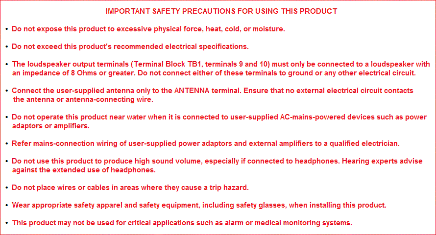
contains devices that may be damaged by static electricity.
Before removing the product
from its
protective shielding bag, discharge static
electricity
that may have accumulated on your body by touching a grounded metal
object
near your work area. Remove the product in a work area
specifically
designed to prevent the accumulation of static electric charges, and
use
caution to prevent static discharges when handling the assembly prior
to
its final installation. The assembly has built-in static protection to
prevent damage from body static discharge to its antenna input and
terminal block (TB1).
- The
recommended antenna assembly, Harrison Instruments item number 99999-5977-006
may be ordered separately. It consists of an antenna plate,
supporting mast, plug,
and jack. The antenna assembly is typically mounted to the enclosure
that houses the Printed Circuit Assembly. The
jack provides electrical insulation for the antenna from the enclosure,
and the mast provides adequate separation between the antenna plate and
enclosure.
- Install
the Printed Circuit Assembly
in an enclosure
with four user-supplied 1/4" or longer metal
standoffs. The Printed
Circuit Assembly is furnished with its GND
(ground)
jumper installed.
With the GND jumper installed, and the assembly mounted in a metal
enclosure with metallic standoffs, the circuit will
automatically ground to the enclosure via the lower-right
mounting
hole. The use of a metallic enclosure will maximize the
electrostatic isolation between the antenna and Printed
Circuit Assembly,
and may be preferred to ensure the ability to obtain maximum
fundamental tonality at the lower part of the pitch range. (In this
case, the "COUPLING" provision may be used to selectively control the
tonality - refer to step 18.) Optionally, a non-metallic
(plastic or
wood) enclosure may be used.
- Provide
a hole in the enclosure for accessing the Printed
Circuit Assembly ZERO CAL
calibration capacitor, to facilitate calibration
with the enclosure cover in place.
- Connect the antenna
assembly jack to the ANTENNA terminal by a wire (item 2, above) not
exceeding 6 inches in length. The antenna lead-in wire should
be routed in a straight path away from the Printed Circuit
Assembly.
Do not run the antenna connecting wire against metallic enclosure walls or
the Printed
Circuit Assembly.
- Items 3 through 11, above, may be
located in or on the enclosure, or be located away from the Printed Circuit
Assembly and connected with suitably-long wires or a cable. Do not connect the 9 volt battery or
otherwise apply power to the Printed
Circuit Assembly until
all the other items have been mounted and connected.
- The Printed
Circuit Assembly
is capable of driving
loudspeakers with an impedance of 8 ohms or greater. When driving an 8
ohm speaker, limit the input voltage within a range between 7.5 and 9.0
volts DC. 16 ohm loudspeakers may also be used, in which case the input
voltage may extend to an upper limit of 13.0 volts
DC. Alternatively, two 8 ohm loudspeakers may be connected in
series
to provide the equivalent of a 16 ohm load. If a loudspeaker is not
used, leave TB1
terminal 9 and 10 unconnected. Terminals
9 and 10, when used, must be
connected only to a
loudspeaker. These terminals must not be connected to
ground or any other circuit, as doing so will damage the assembly. Do
not exceed the maximum load recommendations, as doing so will damage
the assembly.
- The Printed Circuit Assembly has an
integrated circuit (located directly above TB1 terminal 9), to drive
the loudspeaker. This integrated circuit dissipates heat proportional
to to the power supply voltage, and inversely proportional to the
loudspeaker impedance. In applications where
a. the
speaker impedance is at or near the low end of the acceptable range (8
ohms),
b. the
input voltage is at or near the high end of the acceptable range (9.0
volts),
c. the
ambient operating temperature is at or near the recommended limit of
90°F (32.2°C),
adequate ventilation must be provided so that the case temperature of
the integrated circuit does not exceed +140°F (+60°C). This may be
achieved by providing sufficient ventilation for free air exchange, or
providing the integrated circuit with a heat dissipater such as Fischer
Electronik type SMD
A 8 SA attached with 3M™ Thermally Conductive Epoxy Adhesive TC-2707.
The suitable attachment of larger radiators will further reduce heat in
the integrated circuit.
- If required, connect a
user-supplied amplifier to the Output Jack with a 1/4"
shielded cable ("guitar cable"). To
prevent damage to the amplifier or its loudspeaker, initially set the
amplifier to its minimum volume level.
- Remove objects within 3
feet of the antenna.
- To
provide optimal sensing distance, ground the theremin to
earth with a suitable grounding wire. A grounding wire may be attached
to the lower-right mounting pad via a ring terminal under the mounting
screw head, or inserted into TB1 terminal block position 1, 5, or
14. If the theremin is used with a
user-supplied mains-powered amplifier, the grounding will be provided
via the amplifier through the shield connection at the Line Output Jack
(item 5 above). In this case, a separate ground wire
will
not be required. If the theremin is used exclusively with a loudspeaker
connected to terminals 9 and 10, and no grounding is provided, the
theremin will still operate, but with reduced sensing distance.
- Set the Pitch Zero
Potentiometer (item 3, above) and the Loudspeaker Volume Potentiometer
(item 6, above) to mid position. Note that the Loudspeaker Volume
Potentiometer does not control the level at the Line Audio Output Jack
(item 5, above).
- Connect the 9 volt
battery or
a 9 to 12 volt DC power supply to the Printed
Circuit Assembly and set the power switch to
the "on" position. Observe the
correct power polarity, with the positive connection to TB1 pin 13 and
the negative connection to TB1 pin 14.
- Using
the recommended adjustment tool or jewelers'
screwdriver, adjust the ZERO CAL
calibration capacitor so that no tone is evident in the amplifier's
loudspeaker when the hand is removed from the proximity of the antenna,
and
a low-pitch tone is evident when the hand is approximately 24
inches above the antenna. The pitch should rise in frequency as the
hand is moved closer to the antenna. Do not apply excessive force to the ZERO
CAL calibration capacitor. The illustration, below, shows the adjustment range for the capacitor.
- After
calibration is complete, use the Pitch Zero Potentiometer to
fine-adjust the pitch response so that the theremin produces no sound
with the hand completely away from the antenna, and a low tone with the
hand about 24 inches from the antenna, increasing in pitch as the hand
is brought closer. If adjustment of the Pitch Zero
Potentiometer does
not provide the correct response, then readjustment of the ZERO
CAL capacitor may be required.
- Output
tone quality may be
influenced by external interference,
which will vary depending on the instrument's proximity to emissive
sources such as power lines, fluorescent lighting fixtures,
incandescent lamp dimmers, and computers. This interference may be
remedied by moving the theremin away from such sources.
- If
the
output is taken from the Line Output Jack (item 5, above), and
no loudspeaker is required, current consumption may be reduced by
soldering a wire jumper between
the two INH pads. Inserting the jumper will place the on-board
amplifier section in a low-current, standby mode. This feature will
typically reduce the Printed Circuit Assembly operating current from
6.5 milliamperes to 4 milliamperes, and is useful when it is powered
from a battery.
- The
COUPLING pad is provided for optional tone modification via field
coupling
of the local and variable oscillators. This is accomplished by
soldering a short, stiff wire (20 gauge or similar) to the pad
and extending it away from the board. The length of the wire is
user-selected for the degree of coupling desired. Alternatively, a
#2-56 screw or threaded rod of user-selected length may
be inserted through the CPL pad and secured with a nut or nuts. The wire,
screw, or rod may extend either above or below the board. The tone
characteristic will exhibit increased harmonic content with increased
wire, screw, or rod length. Do not
allow the wire or screw to make electrical contact with other parts of
the circuit.
- An
alternative connection diagram, illustrated below, is useful when the
206 Theremin is used for performance applications in which a P.A.
system is present, and a local loudspeaker isn't required. As
shown, a
wire jumper
between
the two INH pads places the on-board amplifier into its
standby
mode to reduce battery current. In addition, by using a
"tip-ring-sleeve" Output Jack, the on-off function is provided by the
insertion or removal of the output cable's plug, eliminating the need
for an On-Off Switch. This automatically disconnects the battery when
the cord is removed, lessening the likelihood of inadvertent battery
consumption between performances. Note that this function
requires the use of an output cable with a "mono" (tip-sleeve) plug,
and not a
stereo plug.
IMPORTANT: When using this connection method, the"tip" of the cable
plug will momentarily contact the "ring" contact in the theremin output
jack as it is inserted. This will cause a large transient, about equal
to the battery voltage, to be present at the P.A. system's input,
causing an extremely loud pop in the loudspeakers, and possibly
damaging them. It is therefore advised to connect the cable plug at the
theremin end first, and the cable plug at the P.A. system's input,
last. As previously stated: To
prevent damage to the amplifier or its loudspeaker, initially set the
amplifier to its minimum volume level.
Alternative Connection Diagram
Ordering Information
Please order through ebay
|
Harrison Instruments
Item Number
|
Shopping Cart
|
|
206
|
Purchase
on ebay
Item
201643436360 |
99999-5977-006

|
Purchase
on ebay
Item
201639602672 |
90-Day
Limited Parts Warranty and Limitation of Liability
(Click
here for details)
Contact Harrison Instruments
sales@harrisoninstruments.com
Harrison Instruments, Incorporated
Post Office Box 9012
Silver Spring, Maryland 20916
301-871-0423
(Back to Harrison
Instruments' Main Page)
©2017, 2019, 2020 Harrison Instruments, Incorporated.
No
part of this page
may be reproduced without express written consent of the copyright
holder.
Information, prices and specifications may change without notice.