 |
VARIABLE-FREQUENCY, VARIABLE-SYMMETRY WAVEFORM GENERATOR
The Variable-Frequency, Variable-Symmetry Waveform Generator described here may be added to the basic Rotating Sprocket Wheel Lissajóus Generator to produce visually stimulating images, especially when displayed on an oscilloscope with a high-persistence phosphor.
This unorthodox implementation purposefully alters the operation of the Lissajóus Generator's U6A and U6B low-pass Sallen-Key filters by interrupting their feedback loops, via analog switches U11A and U11B, at a frequency determined by the Variable-Frequency, Variable-Symmetry Waveform Generator. In doing so, various perturbations in the voltage waveforms at the oscilloscope's X and Y inputs appear as the filters alternately become disrupted, and then approach recovery. While it is not considered a normal practice to operate operational amplifiers this way, the result, in this application, provides an interesting visual display.
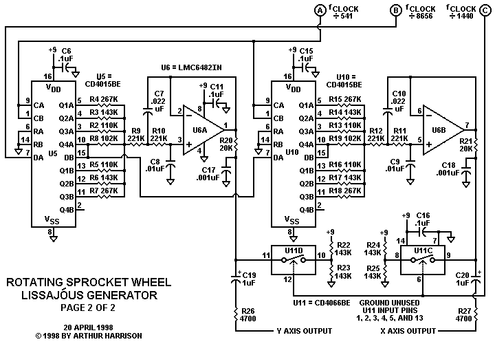
To implement this variation, refer to the basic Rotating Sprocket Wheel Lissajóus Generator schematic, page 2. Disconnect pins 1 and 7 of IC6, as indicated with the red crosses in the following diagram:
|
Construct the Variable-Frequency, Variable-Symmetry Waveform Generator shown below. Note that the two analog switches are leftover sections A and B of U11 from the Lissajóus Generator. Be sure that U11 pins 1, 2, 3, 4, 5, and 13 are disconnected from ground before using them here. The only added ICs are dual op-amps U12 and U13.
 |
Connect ground, the four points labeled A, B, C, and D, and 9 volts between the two generators. Adjust the FREQUENCY and SYMMETRY potentiometers to control the image.
July 6, 2004
Text and images ©2004 by Arthur Harrison
Source documents dated December 16, 1991 and April 26, 1998.
Back to the Rotating Sprocket Wheel Lissajóus Generator
Back to the Circuit Library Index
Back to the Opening Page of Art's Theremin Page