 |
ROTATING SPROCKET WHEEL LISSAJËUS GENERATOR
DESCRIPTION: Jules A. Lissajˇus, a French physicist in the 19th century, described a series of coplanar curves traced by objects executing mutually perpendicular harmonic motions. More than just a mathematic curiosity, his work has been implemented in the era of electronics as a means of measuring the relationship of alternating-current waveforms. A common application of Lissajˇus' observations is demonstrated with the use of an oscilloscope, where one electric waveform is used to control the vertical (y-axis) position of the display beam, and another waveform is used to control the horizontal (x-axis) position. By utilizing this technique, certain relative properties of the waveforms may be revealed. For example, when the waveforms are each sines of equal amplitude, and have a phase relationship of 90 degrees, the resulting image will be a circle. Furthermore, deviations in the amplitudes and relative phase of the two waves will result in alterations of the image's pattern.
The circuit described here utilizes a Lissajˇus-pattern generator in conjunction with any typical analog oscilloscope capable of displaying x- and y-axis waveforms. The circuit displays an image of a slowly clockwise-rotating, six-tooth sprocket wheel. It employs several interesting techniques, including a digital timebase generator, a sine-cosine ("quadrature") synthesizer comprised of two finite-impulse response filters, and an amplitude commutator.
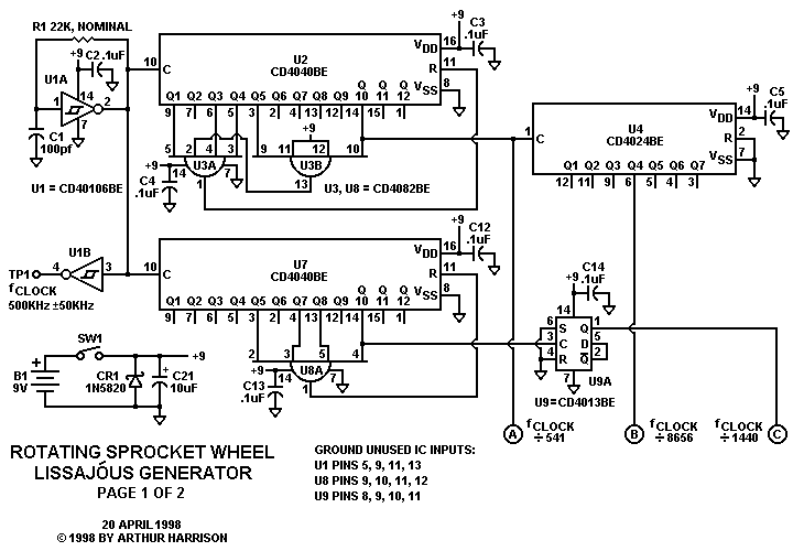
Operation is as follows: IC U1A, an inverting Schmitt trigger, in association with C1 and R1, forms an astable multivibrator (oscillator) with an output frequency of 500kHz ▒50kHz. (Note the wide tolerance; a precise frequency is not critical for this circuit.) The U1B-buffered test point, TP1, is provided to measure the oscillator's frequency for calibration. The frequency may be adjusted by altering the value of R1, nominally specified as 22,000 ohms.
The output of U1A is fed to binary counter IC U2. U2's Q1, Q3, Q4, Q5, and Q10 outputs are connected to a six-input AND gate comprised of IC U3A and B. The output of this gate, U3A pin 1, is fed back to the RESET input of U2, causing it to reset to a value of zero after 541 clock cycles. The frequency of the waveform at U2, pin 14, therefore, is fCLOCK divided by 541, or nominally 924.21 Hz. U4 further divides U2's output by 16, providing a nominal frequency of 57.76 Hz at its Q4 output.
The output of U1A is also fed to binary counter U7. U7's Q5, Q7, Q8, and Q10 outputs are connected to four-input AND gate U8A. The output of this gate, U8A pin 1, is fed back to the RESET input of U7, causing it to reset to a value of zero after 720 clock cycles. The frequency of the waveform at U7, pin 14, therefore, is fCLOCK divided by 720, or nominally 694.44 Hz. U9A further divides U7's output by 2, providing a fifty-percent duty cycle squarewave with a nominal frequency of 347.22 Hz at its Q output.
The absolute frequencies of the three waveforms are of secondary importance, whereas the ratios of these frequencies are the primary determinants of the Lissajˇus pattern's appearance, maintained by the digital dividers.
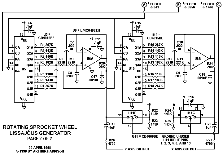
U5 is a dual, 4-bit shift register configured as a single eight-bit, serial-input, parallel-output shift register. fCLOCK divided by 541, designated as point "A" in the schematic, is connected to U5's DATA input, and fCLOCK divided by 8656, designated as point "B," is connected to its CLOCK inputs. Eight cycles of logic ONES and eight cycles of logic ZEROS, provided by U4's output, are alternately clocked through the register.
A finite-impulse response (FIR) filter may be defined as a filter comprised of a tapped delay line connected to a set of weighted elements. In this circuit, the tapped delay line is implemented with a shift register, and the weighted elements are resistors. The 57.76 Hz squarewave presented to the DATA input of U5 is transformed into a stepped-sine approximation at the summing node of the resistors. A useful attribute of this circuit is that it will automatically track the input frequency, thus providing a sine approximation of the DATA input squarewave over a wide range of frequencies.
The stepped-sine approximation is fed to U6A and associated components, configured as a Sallen-Key lowpass analog filter with a cutoff frequency of 45 Hz. (Note that the cutoff value is determined with the parallel combination of R2 through R8 added to R9.) This filter further reduces the amplitude of the waveform's upper harmonics, resulting in a sine wave with suitably low distortion at U6A pin 1.
ICs U10 and U6B are configured identically to U5 and U6A, except the DATA input of U10 is obtained from U5's Q4 output. Thus, the data presented to U10 is shifted four clock cycles with respect to the data at U5, which results in a 90 degree phase relationship between the sinewaves at U6A pin 1 and U6B pin 7, given that the phase shifts in the two Sallen-Key filters are equal.
The outputs of the Sallen-Key filters are fed to analog switches U11C and U11D, that, in conjunction with resistors R20 through R25, form amplitude commutators that alternately switch the sinewave amplitudes between attenuated and unattenuated states and, therefore, alternate the diameter of the Lissajˇus circle between two values. The switches are controlled by fCLOCK divided by 1440, a value intentionally chosen to have a non-integer relationship with the other two frequencies; 8656 divided by 1440 is 6.01. This ratio has a direct bearing on the number of "teeth" in the sprocket image and also, the fact that it appears to rotate approximately once every 8.8 seconds.
Capacitors C17 and C18 are included to integrate waveform spikes occurring at U11 switch transitions which would otherwise appear as artifacts in the display, and also serve to add some definition to the edges of the "teeth." C19 and C20 serve to remove the DC offset of the output waveforms, and R26 and R27 are included to protect the circuit from unintentional applications of voltage at its outputs.
This circuit is easily powered from a single 9-volt battery, and consumes less than 3 milliamperes. Schottky rectifier CR1 protects the circuit from accidental battery reversal, and capacitor C21 provides supply decoupling. The circuit will operate over a range of 6 to 12 volts. With a 9 volt supply, the output waveforms have an amplitude of about 5 volts, peak-to-peak. The LMC6482IN dual operational amplifier IC, U6, may be substituted with a number of alternative types including LMC662CN or LM358N. Type LM833N may also be used at the expense of increased supply current, and types LM1458N or LF353N will work for supplies greater than 8.5 volts.
CONSTRUCTION: The prototype was constructed with Wirewrap(TM) sockets and headers on perforated glass-epoxy board. Most of the discrete components are soldered to headers and plugged into sockets. Each IC socket is furnished with a built-in 0.1uF ceramic bypass capacitor (C2 through C6 and C11 through C16). Functionally-identical logic elements may be interchanged, e.g., the order of of the inputs to AND gate U3 may be changed, and flip-flop U9B may be used in place of U9A, with no consequence. However, the schematic connections are optimized for the suggested layout, provided. The resistors are 1/4-watt, metal film, ▒1% tolerance, except R1, R20, R21, R26, and R27 which are 1/4-watt, carbon film, ▒5% tolerance. Capacitors C7, C8, C9, C10, C17, and C18 are CK05-type X7R dielectric ceramic types chosen for their compact size. C19, C20 and C21 are radial dipped tantalum capacitors with a 20 volt rating.
PARTS LIST: This list was updated September, 2018. As with all parts lists, availability is subject to change:
PARTS FOR ROTATING SPROCKET WHEEL LISSAJËUS GENERATOR
| B1 | 9v Battery | Mouser Electronics stock number 658-6LF22XWA/C |
| C1 | 100pF Axial Ceramic Capacitor | Mouser Electronics stock number 80-C410C101J1G |
| C2, C3, C4, C5, C6, C11, C12, C13, C14, C15, C16 | 0.1uF Axial Ceramic Capacitor | Mouser Electronics stock number 80-C412C104K5R |
| C7, C10 | 0.022uF Axial Ceramic Capacitor | Mouser Electronics stock number 80-C410C223K5R |
| C8, C9 | 0.01uF Axial Ceramic Capacitor | Mouser Electronics stock number 80-C410C103K5R |
| C17, C18 | 0.001uF Axial Ceramic Capacitor | Mouser Electronics stock number 80-C410C102J1G |
| C19, C20 | 1uF Radial Tantalum Capacitor | Mouser Electronics stock number 80-T350A105K025 |
| C21 | 10uF Radial Tantalum Capacitor | Mouser Electronics stock number 80-T350E106K016 |
| CR1 | 1N5820 Axial Silicon Rectifier | Mouser Electronics stock number 863-1N5820G |
| R1 | 22kOhm Carbon Film Resistor | Mouser Electronics stock number 291-22K-RC |
| R2, R5, R13, R16 | 110kOhm Metal Film Resistor | Mouser Electronics stock number 603-MFR-25FBF52-110K |
| R3, R6, R14, R17, R22, R23, R24, R25 | 143kOhm Metal Film Resistor | Mouser Electronics stock number 603-MFR-25FBF52-143K |
| R20, R21 | 20kOhm Carbon Film Resistor | Mouser Electronics stock number 291-20K-RC |
| R26, R27 | 4.7kOhm Carbon Film Resistor | Mouser Electronics stock number 291-4.7K-RC |
| R4, R7, R15, R18 | 267kOhm Metal Film Resistor | Mouser Electronics stock number 603-MFR-25FBF52-267K |
| R8, R19 | 102kOhm Metal Film Resistor | Mouser Electronics stock number 603-MFR-25FBF52-102K |
| R9, R10, R11, R12 | 221kOhm Metal Film Resistor | Mouser Electronics stock number 603-MFR-25FBF52-221K |
| SW1 | Toggle Switch, SPST | Mouser Electronics stock number 633-M201101 |
| U1 | CD40106BE Hex Inverting Schmitt Trigger Integrated Circuit | Mouser Electronics stock number 595-CD40106BE |
| U2 & U7 | CD4040BE Digital Counter Integrated Circuit | Mouser Electronics stock number 595-CD4040BE |
| U3 & U8 | CD4082BE Dual 4-Input And Gate Integrated Circuit | Mouser Electronics stock number 595-CD4082BE |
| U4 | CD4024BE Digital Counter Integrated Circuit | Mouser Electronics stock number 595-CD4024BE |
| U5 & U10 | CD4015BE Dual 4-Bit Shift Register Integrated Circuit | Mouser Electronics stock number 595-CD4015BE |
| U6 | LMC6482IN Dual CMOS Operational Amplifier Integrated Circuit | Mouser Electronics stock number 926-LMC6482IN/NOPB |
| U9 | CD4013BE Dual D-Type Flip-Flop Integrated Circuit | Mouser Electronics stock number 595-CD4013BE |
| U11 | CD4066BE Quad Analog Switch Integrated Circuit | Mouser Electronics stock number 595-CD4066BE |
| Miscellaneous Items | Circuit Board, IC Sockets, Component Terminals, Component Headers, Wire,
Battery Connector, Circuit Board Standoffs and Fastening Hardware, Enclosure, Output Connectors |
- |
VARIATIONS: The circuit, as shown, is only one of many
variations which may be easily modified to produce interesting results. Simply
exchanging the two output connections will result in a counterclockwise rotation
of the image. A variable delay placed between the output of AND gate U8A
and the RESET input of U7 will allow alterations in the rate and direction
of the image's rotation. Removing IC U6 will greatly alter the image by defeating
the Sallen-Key filters, replacing them with complex passive networks. Adding
a second divide-by-two flip flop between U7 and U9 will reduce the number
of "teeth" in the the image from six to three.
Very complex images can be created by placing analog switches directly in series with each operational amplifier output, and controlling the switches with a Variable-Frequency, Variable-Symmetry Waveform Generator. The latter variation produces visually stimulating images, especially on an oscilloscope with a high-persistence phosphor. Another possibility is the addition of multiplexing, blanking, and phase-reversing circuitry to display two or more meshing wheels, displayed on an oscilloscope with z-axis (blanking) capability.
See my friend Matt Bennett's version of this generator, using the Microchip Technology, Inc. type 16F84 programmable integrated circuit, at http://tinymicros.com/wiki/Rotating_Sprocket_Wheel_Generator.
 |
 |
|
April 26, 1998
April 10, 2004
September 13, 2018
Text and images ę1998, 2004, 2018 by Arthur Harrison
Source documents dated September 20, 1990
Back to the Circuit Library Index
Back to the Opening Page of Art's Theremin Page