The 125 Vacuum Tube Pitch Theremin
Published July 13, 2002
Updated February 1, 2020
Legal Notice
Safety Notices
Introduction
Circuit Description
Schematics
Construction
Test Voltages
Parts Tables
Drawing Index
Legal Notice
(back to contents)
The information contained in this document is ©2002, 2003, 2014, 2020 by Arthur Harrison. Any reproduction of the information contained in this document, electronic or mechanical, shall only be used with Arthur Harrison's permission, and shall acknowledge him as the copyright holder and author.
Use of the information contained in this document for personal or commercial financial gain, such as the manufacture and sale of electronic musical instruments or parts thereof, is prohibited. Unless specifically stated in a written contract, Arthur Harrison grants no license for the commercial exploitation of the concepts and designs embodied in this document. Refer licensing inquiries to: diy@harrisoninstruments.com.
The information contained in this document may only be reproduced in small quantities when the purpose for its use is the dissemination of information to students or hobbyists, and may not be distributed in any form, electronic or mechanical, for the purposes of any party engaged, directly or indirectly, in commercial enterprises.
Arthur Harrison assumes no liability for any damages, direct, or consequential, which may arise from the dissemination, application, or misapplication of the content contained in this site. The User of the information provided in this site assumes all responsibility for any damages, direct or consequential, which may arise from its use. Arthur Harrison retains the right to alter the content within this site at any time without notice.
Safety
Notices
(back to contents)
The circuit described in this article uses AC mains
voltage and other high voltages that can cause injury or death. It is
the responsibility of the user of this circuit to be familiar with all applicable
safety practices regarding its construction, testing, and
use.
Some parts used in this circuit only function properly
when inserted in the right direction. Always verify the orientation of polarized
capacitors, diodes, rectifiers, transformers and vacuum tubes before applying
power to them. Do not use a part that has been subjected to improper
insertion.
The vacuum tubes in this circuit become hot and
can cause burns.
Wear safety glasses and use all appropriate safety equipment when working with tools and materials. Always follow safe shop practices and obey safety rules.
Regarding the safety of your ears and hearing:
This circuit is recommended for users familiar with electronic theory and construction practices. It is recommended that suitable test equipment, including a frequency counter and oscilloscope, be available for making measurements.
Introduction
(back to contents)
In this article, I take departure from solid-state theremins to investigate the use of vacuum tubes, the staple of Leon Theremin's original instruments. My interest was prompted by numerous requests from theremin builders who required a tested, well documented design. This theremin only has a provision for pitch control, with a more comprehensive all-tube design, featuring a volume circuit, to follow at a later date.
The 125 is a basic heterodyne configuration, in which the outputs of two similar radio-frequency Colpitts oscillators are fed to a mixer, producing their difference frequency as an audible tone. A popular vacuum tube, the dual-triode 12AU7 (or its European equal type ECC82), is specified. Exceptional frequency stability for temperature variation is achieved, thanks to the low temperature coefficient of tube interelectrode capacitance, first-order cancellation between the two similar oscillators, and the use of stable frequency-determining inductors and capacitors. In fact, the temperature stability of the 125 theremin rivals that of many, much more complex, solid-state instruments.
While a second resonant circuit is used in some theremin pitch variable oscillators to increase hand-sensing distance, the 125 theremin excludes these components, compensating the loss with a flat antenna that presents better capacitance-coupling efficiency than the traditional monopole type. It is still possible to use a monopole antenna with this design, but with a reduction in sensing distance. With it's 6-inch-square flat antenna, the 125 exhibits at least 4 octaves of pitch variation over a sensing distance of about 16 inches, as illustrated in the following graph:
The amount of coupling between the oscillators, and their waveshapes; and
the transfer characteristics of the mixer, filter, and audio amplifier stages
all are factors determining a heterodyne theremin's tonal character. In this
design, the electrical, and to a lesser extent, magnetic coupling of the
two oscillators, create waveform characteristics that dominate the timbre.
Certain unique qualities of vacuum tubes may also be a factor affecting tone
quality. The 125 theremin may be heard by clicking on the MP3 link below.
(258 kilobytes):
Circuit Description
(back to contents)
V1 and associated circuitry is a variable oscillator which changes frequency with hand capacitance, and V3 is a reference oscillator. The oscillators employ cathode-follower sections, V1B and V3B, to buffer their resonant networks from loading effects and to provide low impedance outputs. V2A is used as a mixer, with the variable oscillator output applied to its grid via DC blocking capacitor C6 and the reference oscillator output applied to its cathode via DC blocking capacitor C12.
Electrical coupling between the two oscillators occurs because the signal at V2A's cathode includes the signal present at it's grid. This signal, from the variable oscillator, is reflected back into the reference oscillator. A variation in tone quality can be readily achieved by disconnecting C6 from the grid of V2A and reconnecting it to to the cathode of V2A. If this is done, also connect a shorting wire across R11. The tone variation that results from this modification occurs because of diminished electrical coupling between the two oscillators. In addition to modifying the timbre, the amplitude of the audio output will be reduced approximately seventy percent. (The text and above sound sample represents the circuit as shown in the schematic, without modification.)
The heterodyne of the two oscillator frequencies is present at V2A's plate. Two sections of low-pass filtering reduce the sum frequency product; C14 in conjunction with V2A's plate-circuit resistance, and R15 with C15. Capacitor C16 blocks the DC voltage at V2A's plate from the following stage. V2B is a cathode-follower that provides a suitably low impedance for the audio output. C17 further reduces sum frequency products to an insignificant amplitude. Capacitor C20 blocks DC from the output, and resistor R18 discharges residual voltage in C20 to prevent a transient in the external amplifier system upon connection. The theremin's output is intended to drive the high input impedance of an amplifier or production board, providing a maximum amplitude of about 2 volts, peak-to-peak. Accordingly, most guitar amplifiers have too much gain for this instrument, and must be equipped with a suitable input attenuator.
The oscillator frequencies of approximately 310kHz are described by the following equation, where L is 1mh, Ca is 1000pF, Cb is 330pF, and Cc is the antenna capacitance (for the variable oscillator) or the value of the C10 pitch-zeroing capacitor (for the reference oscillator):

As in any heterodyne theremin, a key issue is making the two oscillators very close in frequency, so that an audible tone can be produced. Optimally, the instrument should provide a "zero-beat" condition with C10 set to its mid-capacitance point, with the hand away from the pitch antenna. A low frequency audible output, evident as pulsations, should result when the hand is brought within 12 to 24 inches of the antenna, increasing in frequency as the hand becomes closer.
In most instances, component tolerances will cause the oscillator frequencies
to be too far apart to produce an audible tone, so a calibration procedure
must be performed. To do this, measure the frequency of the reference oscillator
by connecting a counter to the cathode of V3B, and record that frequency.
Then, move the counter to the cathode of V1B, which is the output of the
variable oscillator. With variable capacitor C10 set to midpoint, and the
antenna inserted and clear of objects, adjust the frequency of the variable
oscillator to match the recorded frequency, with one or more of the following
methods:
To reduce the variable oscillator's frequency, add a small mica capacitor
between 2 and 30pF in parallel with its coil (L1).
To increase the variable oscillator's frequency, replace 330pF capacitor
(C4) with a 300pF mica unit, and then, if necessary, add a small mica capacitor
(between 2 and 15pF) in parallel with the 300pF unit to "trim" the frequency
back downward.
Move L1 toward or away from the metal mounting plate; toward the mounting plate for decreasing frequency, and away from the mounting plate for increasing frequency.
To eliminate the necessity for extensive trimming, C3, C4, C8, and C9 should have ±5% or better tolerances. To ensure good frequency stability, these four capacitors should be mica types, and the two coils, L1 and L2, should be the J.W. Miller 4652 phenolic-core types specified. Capricious substitution of the coils may adversely affect or inhibit the theremin's operation. While the overall frequency of the theremin's operation may be changed with the substitution of oscillator frequency-determining components, the values indicated, for approximately 310kHz, were selected to prevent AM radio-band interference, while maintaining an adequate hand-sensing distance.
Also for frequency stability, C10 should be the air-variable variety. Although variable capacitors of substantially larger values than the one specified are commonplace, too much capacitance change per degree of shaft rotation will make zeroing the pitch difficult. Therefore, the maximum value of 27pF is recommended to ensure adequate adjustment resolution. A variable capacitor with a planetary reduction vernier will further enhance the ability for precise pitch zeroing. Such a capacitor, with about 4 turns of shaft rotation, is indicated in the schematic and highly recommended.
Voltage regulation is not employed in this circuit, since the oscillators exhibit excellent frequency stability with considerable supply variations. To minimize the amount of supply-induced audio hum and adverse RF coupling, tube plate circuits V1A, V2A, and V3A are individually bypassed with a resistor and capacitor. The total current drawn from the 50 volt supply is approximately 1.8mA. Heater transformer T2 is rated to provide 10 volts RMS for a 1.2A load. The three tubes use approximately 450mA of heater current, so T1's actual loaded output is about 12 volts RMS, which is adequate for the 12.6 volt-rated 12AU7s or ECC82s.
To reduce the risk of injury, I designed this theremin with a maximum supply of approximately 50 volts, DC, which is considerably less than voltages used in many other vacuum-tube instruments. However, values substantially less than 50 volts can still be dangerous for conditions in which sufficient current is caused to flow through the body. Therefore, 330pF ceramic capacitor C1 provides a safety function by preventing the presence of +50 volts on the antenna.
SAFETY NOTICE:
Do not omit capacitor C1 from the circuit.
![]()
Construction
(back to contents)
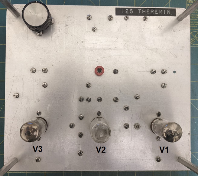
The breadboard for this theremin is constructed on a 10" x 12", 1/16"-thick aluminum mounting plate. For performance purposes, the mounting plate can be attached to a 10" x 12" x 3" aluminum chassis such as the Bud Industries type AC-413, equipped with an Atlas Sound type AD-11B threaded microphone stand adapter, as illustrated.
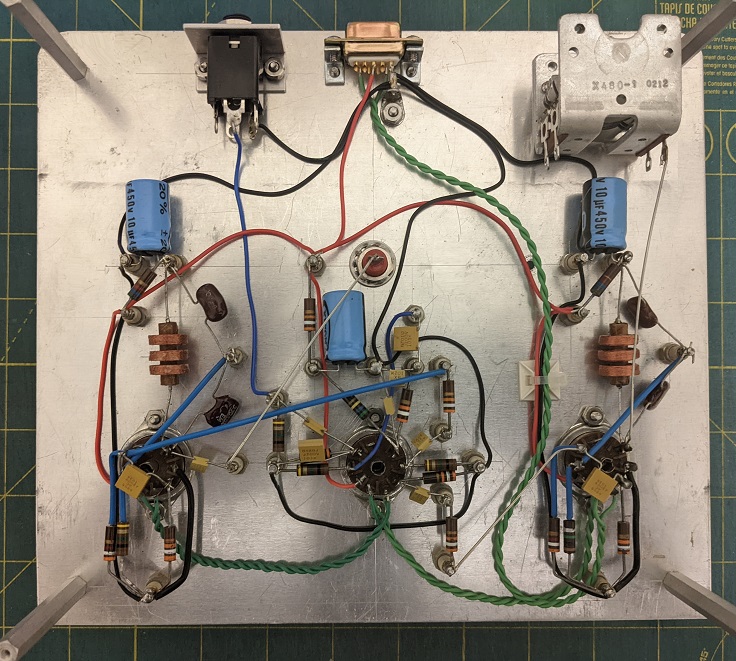
Refer to the Mounting Plate Hole Locations drawing. (Note: The drawing is intended for dimensional references only, and should not be used as a template.) Components and tube sockets are mounted on the bottom of the mounting plate, with the shaft for C10, tubes, and antenna assembly on the top. The three 9-pin tube sockets are mounted in a straight line, with 2 3/4" spacing between them. These tube sockets are the "top-mountable" variety, which require 3/4" holes that can be made with a chassis punch such as the Greenlee type 730BB-3/4. The Antenna Assembly plugs into banana jack J4, mounted through the mounting plate. Power connector J3 and output jack J5 are mounted on small right-angle Brackets attached to the bottom of the mounting plate. The two steel brackets for the power connector are similar to Keystone Electronics type 621, which may be modified to meet the requirement. A rectangular cut-out in the chassis allows access to J3 and J5.
Screw-mounted Insulated Solder Turret Terminals provide junction points. Where required, component leads are insulated with 16 gauge Teflon® sleeving. Point-to point wiring is used, with 22 gauge, 19-strand Teflon®-insulated hookup wire, and 20 gauge solid tinned-copper bus wire, as required. Wires are anchored to the mounting plate, as required, with adhesive-backed mounts and nylon cable ties.
During construction, eight 2-inch long standoffs attach to the mounting plate's corner holes to support the chassis. Four of them are standard types, and four are "male/female" types. Each male/female spacer has a stud that is inserted through a hole to engage its corresponding standard spacer. If a chassis is not added to the theremin, then the lower four standoffs may be retained as legs, and the male/female spacers replaced with screws.
For specific component placement, refer to the Component Locations drawing. When soldering coils L1 and L2 to their turret terminals, leave a little slack in their leads so that they can be moved toward and away from the mounting plate. This technique permits small variations in capacitance that may be used to fine-adjust oscillator frequencies. Make the connections between antenna jack J4, C1, and pin 1 of the V1 socket with rigid bus wire shaped to avoid close proximity with other components. Keep frequency-determining components C3, C4, C8, C9, L1 and L2 clear of other parts and wires. To prevent audible hum from the heater circuit, twist the heater wires tightly together and route them in a direct manner away from signal paths.
While ground wiring can be "daisy-chained" within each circuit section, run a wire from each chain, as well as terminal 1 of power connector J3, to a single point on the metal chassis. The J5 output jack is a fully insulated type, to prevent audible hum from ground loop currents. Its sleeve terminal connects to the single-point ground, as well. The type of variable capacitor used in the breadboard has its "rotor" terminal connected to its frame, and therefore becomes electrically grounded by mechanical attachment to the mounting plate. C10's four solder lugs are redundant "stator" terminals, of which only one is connected to V3A's plate.
For safety, power supply components J1, F1, SW1, T1, T2, BR1, and C19 (shown on schematic page 2) are fully enclosed in a 5" x 6" x 4" steel utility cabinet, separate from the main assembly. J1 is an AC power inlet that mates with a 3-wire, grounded cord identical to the type used for most computers and test equipment. For construction simplicity, all the power supply parts are mounted to the inside surface of the utility cabinet's top panel, as illustrated in the Power Supply Lay-out drawing . Adhesive-backed mounts and nylon cable ties are used to secure wires as required. The inlet, fuse holder, switch, and transformer terminals are insulated with 1/8" or 1/4"-diameter heat-shrink tubing, as required. Four self-adhesive feet are applied to the cabinet's bottom panel.
A four-wire extension cable with 9-pin "D" subminiature connectors connect
the theremin assembly and power supply together. The length of the extension
is optional, with about four feet being typical for extending from the floor
to the top of a stand.
SAFETY NOTICES: To prevent shock hazards from
lethal mains voltage:
Test Voltages
(back to contents)
The following voltages are from the 125 theremin breadboard, measured with a Tektronix type 485 oscilloscope, and a 10Mohm, 10X-attenuation probe. Measurements are made with A1 replaced by an equivalent capacitance, (typically 10pF, mica) connected from J4 to ground, and a line input of 117 volts RMS. V1 or V3 are removed for some steps to simplify measurements. Audio frequencies are obtained by adjusting C10. Unless otherwise noted, values may vary ±20% among different circuits due to component tolerances.
- |
TEST POINT |
REMOVE | VALUE |
| B+ | BR1+ | - |
+47.5 ±3VDC with less than 60mV P-P of 60Hz + RF modulation |
| V1A plate | V1-1 | V3 | 32V P-P RF sine wave centered at +47VDC |
| V1A grid | V1-2 | V3 | 0V (ground) |
| V1A cathode | V1-3 | V3 | 5V P-P RF approximate sine wave centered at +4.25V |
| V1B plate | V1-6 | V3 | +47.5VDC with less than 60mV P-P of 60Hz + RF modulation |
| V1B grid | V1-7 | V3 | 8V P-P RF sine wave centered at 0V |
| V1B cathode | V1-8 | V3 | 5V P-P RF approximate sine wave centered at +4.25VDC |
| V3A plate | V3-1 | V1 | 32V P-P RF sine wave centered at +47VDC |
| V3A grid | V3-2 | V1 | 0V (ground) |
| V3A cathode | V3-3 | V1 | 5V P-P RF approximate sine wave centered at +4.25V |
| V3B plate | V3-6 | V1 | +47.5VDC with less than 60mV P-P of 60Hz + RF modulation |
| V3B grid | V3-7 | V1 | 8V P-P RF sine wave centered at 0V |
| V3B cathode | V3-8 | V1 | 5V P-P RF approximate sine wave centered at +4.25VDC |
| V2A plate | V2-1 | - |
+17VDC with: <70mV P-P RF for zero audio beat 2.5V P-P with C10 adjusted for audio output of 110Hz 2.5V P-P with C10 adjusted for audio output of 220Hz 2.0V P-P with C10 adjusted for audio output of 440Hz 1.2V P-P with C10 adjusted for audio output of 880Hz 0.8V P-P with C10 adjusted for audio output of 1760Hz 0.5V P-P with C10 adjusted for audio output of 3520Hz |
| V2A grid | V2-2 | V3 | 200mV P-P RF approximate sine wave centered at 0V |
| V2A cathode | V2-3 | V1 | 600mV P-P RF approximate sine wave centered at +1.7VDC |
| V2B plate | V2-6 | - |
+47.5VDC with less than 60mV P-P of 60Hz + RF modulation |
| V2B grid | V2-7 | - |
0VDC with: <10mV P-P RF for zero audio beat 2.5V P-P with C10 adjusted for audio output of 110Hz 2.5V P-P with C10 adjusted for audio output of 220Hz 2.0V P-P with C10 adjusted for audio output of 440Hz 1.2V P-P with C10 adjusted for audio output of 880Hz 0.8V P-P with C10 adjusted for audio output of 1760Hz 0.5V P-P with C10 adjusted for audio output of 3520Hz |
| V2B cathode | V2-8 | - |
2.2VDC with: <5mV P-P RF for zero audio beat 2.0V P-P with C10 adjusted for audio output of 110Hz 2.0V P-P with C10 adjusted for audio output of 220Hz 1.6V P-P with C10 adjusted for audio output of 440Hz 1.0V P-P with C10 adjusted for audio output of 880Hz 0.6V P-P with C10 adjusted for audio output of 1760Hz 0.4V P-P with C10 adjusted for audio output of 3520Hz |
Parts Tables
(back to contents)
Schematic-designated items are indicated in the first table, and other items are in the second table. Identical items, such the flat washer used for both mounting the tube sockets and the terminals, appear on more than one line. Suppliers indicated are not necessarily exclusive sources.
Notes:
†Used in mounting plate and chassis assembly, or in extension cable
*Used in power supply assembly
#The following manufacturers make transformers similar to the Signal Transformer
Company types indicated in the table:
Triad Magnetics:
http://www.triadmagnetics.com/home.htm.
Refer to their "Quick Pack" (TM) product line.
Magnetic Coils, Inc.:
http://www.mcitransformer.com/.
Refer to their "Quick Connect Power Transformers" product line.
Hammond Manufacturing:
http://www.hammondmfg.com/. Refer
to their "186/187" product line.
A/R = as required
| LINE | ITEM | DESCRIPTION | VALUE | MANUFACTURER |
MANUFACTURER PART |
SUPPLIER | SUPPLIER STOCK NUMBER |
QTY |
| 01† | A1 | ANTENNA | (Antenna parts listed in Table 2) | . | . | . | . | 1 |
| 02* | BR1 | RECTIFIER BRIDGE |
6A, 200V |
RECTRON | BR62 | MOUSER ELECTRONICS |
583-BR62 | 1 |
| 03† | C1 | CERAMIC CAPACITOR |
330pF ±10%, X7R, 200V, RADIAL |
AVX | CK05BX331K | MOUSER ELECTRONICS |
581-CK05BX331K | 1 |
| 04† | C4, C9 |
MICA CAPACITOR |
330pF ±5%, 500V |
CORNELL DUBILIER |
CD19FD331JO3 | MOUSER ELECTRONICS |
5982-19-500V330 | 2 |
| 05† | C2, C7, C13 |
ELECTROLYTIC CAPACITOR |
10uF ±20%, 100V, 105°C, RADIAL, 6.3mm D x 11mm L |
NICHICON | UPW2A100MED | MOUSER ELECTRONICS |
647-UPW2A100MED | 3 |
| 06† | C3, C8 | MICA CAPACITOR |
1000pF ±5%, 500V |
CORNELL DUBILIER |
CD19FD102JO3 | MOUSER ELECTRONICS |
5982-19-500V1000 | 2 |
| 07† | C5, C11, C16, C17, C18 |
CERAMIC CAPACITOR |
0.01uF ±10%, X7R, 200V, RADIAL |
AVX | CK06BX103K | MOUSER ELECTRONICS |
581-CK06BX103K | 5 |
| 08† | C6, C12, C14, C15 |
CERAMIC CAPACITOR |
1000pf ±10%, X7R, 200V, RADIAL |
AVX | CK05BX102K | MOUSER ELECTRONICS |
581-CK05BX102K | 4 |
| 09† | C10 | AIR VARIABLE CAPACITOR |
6.2-27pF, 8:1 VERNIER |
HARRISON INSTRUMENTS |
99999-5910-7-27R0 | HARRISON INSTRUMENTS |
99999-5910-7-27R0 | 1 |
| 10* | C19 | ELECTROLYTIC CAPACITOR |
330uF ±20%, 100V, 85°C, AXIAL, 13mm D x 31.5mm L |
NICHICON |
TVX2A331MCD | MOUSER ELECTRONICS |
647-TVX2A331MCD | 1 |
| 11* | F1 | CARTRIDGE FUSE | 1/8A, 250V, SLOW-ACTING 0.25" D x 1.25" L |
LITTELFUSE | 0313.125MXP | MOUSER ELECTRONICS |
576-0313.125MXP | 1 |
| 12* | J1 | AC INLET | 250VAC, 15A, IEC TYPE 60320-1 C14 |
KOBICONN | 161-0707-1-E | MOUSER ELECTRONICS |
161-0707-1-E | 1 |
| 13* | J2 | CONNECTOR | 9 POSITION, FEMALE CONTACTS, D-SUBMINIATURE |
AMPHENOL FCI |
DEO09S065TLF | MOUSER ELECTRONICS |
649-DEO09S065TLF | 1 |
| 14† | J3 | CONNECTOR | 9 POSITION, MALE CONTACTS, D-SUBMINIATURE |
AMPHENOL FCI | DE09P064TXLF |
MOUSER ELECTRONICS |
649-DE09P064TXLF | 1 |
| 15† | J4 | BANANA JACK | INSULATED, NYLON, RED, 5/16"-32 UNEF-2A THREAD |
JOHNSON COMPONENTS |
108-0902-1 | MOUSER ELECTRONICS |
530-108-0902-1 | 1 |
| 16† | J5 | PHONE JACK | 1/4", INSULATED, MONOPHONIC |
SWITCHCRAFT | N111X | MOUSER ELECTRONICS |
502-N-111X | 1 |
| 17† | L1, L2 | INDUCTOR, THREE-SECTION, UNIVERSAL "PIE" WOUND |
1mH ±5%, 19 OHM, Q=59 @ 0.25MHz, SRF=3.7MHz MINIMUM |
J.W. MILLER | 4652 | HARRISON INSTRUMENTS |
96804-4652 | 2 |
| 18† | P1 | CONNECTOR | 9 POSITION, MALE CONTACTS, D-SUBMINIATURE |
AMPHENOL FCI | DE09P064TXLF | MOUSER ELECTRONICS |
649-DE09P064TXLF | 1 |
| 19† | P2 | CONNECTOR | 9 POSITION, FEMALE CONTACTS, D-SUBMINIATURE |
AMPHENOL FCI | DEO09S065TLF | MOUSER ELECTRONICS |
649-DEO09S065TLF | 1 |
| 20† | R1,R6 | RESISTOR | 5600 OHM ±5%, 1/2W, CARBON FILM |
XICON | 293-5.6K-RC | MOUSER ELECTRONICS |
293-5.6K-RC | 2 |
| 21† | R2, R7, R5, R10, R12, R14, R15 |
RESISTOR | 39K OHM ±5%, 1/2W, CARBON FILM |
XICON | 293-39K-RC | MOUSER ELECTRONICS |
293-39K-RC | 7 |
| 22† | R3, R8, R11, R16, R18 |
RESISTOR | 1M OHM ±5% 1/2W, CARBON FILM |
XICON | 293-1M-RC | MOUSER ELECTRONICS |
293-1M-RC | 5 |
| 23† | R4, R9, R17 |
RESISTOR | 3900 OHM ±5% 1/2W, CARBON FILM |
XICON | 293-3.9K-RC | MOUSER ELECTRONICS |
293-3.9K-RC | 3 |
| 24† | R13 | RESISTOR | 560K OHM ±5% 1/2W, CARBON FILM |
XICON | 293-560K-RC | MOUSER ELECTRONICS |
293-560K-RC | 1 |
| 25* | SW1 | SWITCH, TOGGLE |
6A, 250V, SPDT |
NKK | M2012SS1W01 | MOUSER ELECTRONICS |
633-M201201 | 1 |
| 26*# | T1 | TRANSFORMER | PRIMARY: 120V, 60Hz SECONDARY: 28V, 85mA |
BEL SIGNAL TRANSFORMER COMPANY |
241-3-28 | MOUSER ELECTRONICS |
530-241-3-28 |
1 |
| 27*# | T2 | TRANSFORMER | PRIMARY: 120V, 60Hz SECONDARY: 10V, 1.2A |
BEL SIGNAL TRANSFORMER COMPANY |
241-5-10 | MOUSER ELECTRONICS |
241-5-10 | 1 |
| 28† | V1, V2, V3 |
VACUUM TUBE, DUAL TRIODE |
. | JJ ELECTRONIC |
12AU7 / ECC82 | ANTIQUE ELECTRONICS SUPPLY |
T-12AU7-JJ | 3 |
| LINE | ITEM | DESCRIPTION | MANUFACTURER |
MANUFACTURER PART |
SUPPLIER | SUPPLIER STOCK NUMBER |
QTY |
| 01† | MOUNTING PLATE | 12" x 10" x 0.062" THICK, TEMPER T-6, ALLOY 6061, ALUMINUM (Cut to size for mounting plate) |
N/A | (Use description) | MCMASTER-CARR | 89015K37 | 1 |
| 02† | BRACKET, OUTPUT JACK | (Refer to drawing) | . | . | . | . | 1 |
| 03† | MACHINE SCREW, BRACKET, OUTPUT JACK |
PAN HEAD, SLOTTED, 4-40 x 0.312", STAINLESS STEEL |
. | . | MCMASTER-CARR | 91792A107 (package of 100) |
2 |
| 04† | FLAT WASHER, BRACKET, OUTPUT JACK |
#4, 0.250" O.D., STAINLESS STEEL |
. | . | MCMASTER-CARR | 98019A309 (package of 500) |
2 |
| 05† | LOCK WASHER, BRACKET, OUTPUT JACK |
#4 SPLIT-RING, 0.209" O.D., STAINLESS STEEL |
. | . | MCMASTER-CARR | 92146A530 (package of 100) |
2 |
| 06† | MACHINE SCREW NUT, BRACKET, OUTPUT JACK |
HEX, 4-40 x 0.250", STAINLESS STEEL |
. | . | MCMASTER-CARR |
91841A005 (Package of 100) |
2 |
| 07† | BRACKET, POWER CONNECTOR | (Refer to drawing) | . | . | . | . | 2 |
| 08† | MACHINE SCREW, BRACKET, POWER CONNECTOR |
PAN HEAD, SLOTTED, 4-40 x 0.250", STAINLESS STEEL |
. | . | MCMASTER-CARR | 91792A106 (Package of 100) |
2 |
| 09† | FLAT WASHER, BRACKET, POWER CONNECTOR |
#4, 0.250" O.D., STAINLESS STEEL |
. | . | MCMASTER-CARR | 98019A309 (package of 500) |
2 |
| 10† | LOCK WASHER, BRACKET, POWER CONNECTOR |
#4 SPLIT-RING, 0.209" O.D., STAINLESS STEEL |
. | . | MCMASTER-CARR | 92146A530 (package of 100) |
2 |
| 11† | STANDOFF, MOUNTING PLATE TOP | 6-32 x 2" L, MALE/FEMALE, HEXAGONAL, ALUMINUM |
KEYSTONE ELECTRONICS |
8425 | MOUSER ELECTRONICS |
534-8425 | 4 |
| 12† | STANDOFF, MOUNTING PLATE BOTTOM |
6-32 x 2" L, HEXAGONAL, ALUMINUM |
KEYSTONE ELECTRONICS |
2214 | MOUSER ELECTRONICS |
534-2214 | 4 |
| 13† | MACHINE SCREW, STANDOFF | PAN HEAD, SLOTTED, 6-32 x 0.375", STAINLESS STEEL |
. | . | MCMASTER-CARR |
91792A146 (package of 100) |
4 |
| 14† | FLAT WASHER, STANDOFF | #6, 0.313" O.D., STAINLESS STEEL |
. | . | MCMASTER-CARR | 98019A314 (package of 500) |
4 |
| 15† | LOCK WASHER, STANDOFF | #6 SPLIT-RING, 0.250" O.D., STAINLESS STEEL |
. | . | MCMASTER-CARR | 92146A540 (package of 100) |
4 |
| 16† | SOCKET, TUBE | 9-PIN, MINIATURE, 0.750" DIAMETER MTG HOLE, TOP-MOUNTED |
BELTON | VT9-ST-1 | TUBE DEPOT |
SK-B-VT9-ST-2 | 3 |
| 17† | MACHINE SCREW, TUBE SOCKET | PAN HEAD, SLOTTED, 4-40 x 0.313", STAINLESS STEEL |
. | . | MCMASTER-CARR | 91792A107 (package of 100) |
6 |
| 18† | MACHINE SCREW NUT, TUBE SOCKET | HEX, 4-40 x 0.250", STAINLESS STEEL |
. | . | MCMASTER-CARR |
91841A005 (Package of 100) |
6 |
| 19† | FLAT WASHER, TUBE SOCKET | #4, 0.250" O.D., STAINLESS STEEL |
. | . | MCMASTER-CARR | 98019A309 (package of 500) |
6 |
| 20† | LOCK WASHER, TUBE SOCKET | #4 SPLIT-RING, 0.209" O.D., STAINLESS STEEL |
. | . | MCMASTER-CARR | 92146A530 (package of 100) |
6 |
| 21† | KNOB, VARIABLE CAPACITOR | 1.32" D, 0.69" H, FOR 0.250" SHAFT, PHENOLIC, BLACK |
EAGLE PLASTICS | 45KN014-GRX | MOUSER ELECTRONICS |
45KN014-GRX | 1 |
| 22† | MACHINE SCREW, VARIABLE CAPACITOR |
PAN HEAD, SLOTTED, 6-32 x 0.250", STAINLESS STEEL |
. | . | MCMASTER-CARR | 91792A144 (package of 100) |
3 |
| 23† | FLAT WASHER, VARIABLE CAPACITOR |
#6, 0.313" O.D., STAINLESS STEEL |
. | . | MCMASTER-CARR | 98019A314 (package of 500) |
3 |
| 24† | LOCK WASHER, VARIABLE CAPACITOR |
#6 SPLIT-RING, 0.250" O.D., STAINLESS STEEL |
. | . | MCMASTER-CARR | 92146A540 (package of 100) |
3 |
| 25†* | TERMINAL | INSULATED, SOLDER TURRET, 4-40 INTERNAL THREAD |
WEARNES CAMBION |
572-4814-01-05-16 | BISCO INDUSTRIES |
572-4814- 01-05-16 |
25 |
| 26†* | MACHINE SCREW, TERMINAL | PAN HEAD, SLOTTED, 4-40 x 0.250", STAINLESS STEEL |
. | . | MCMASTER-CARR | 91792A106 (package of 100) |
25 |
| 27†* | FLAT WASHER, TERMINAL | #4, 0.250" O.D., STAINLESS STEEL |
. | . | MCMASTER-CARR | 98019A309 (package of 500) |
25 |
| 28†* | LOCK WASHER, TERMINAL | #4 SPLIT-RING, 0.209" O.D., STAINLESS STEEL |
. | . | MCMASTER-CARR | 92146A530 (package of 100) |
25 |
| 29† | ANTENNA | 12" x 12" x 0.062" THICK, TEMPER T-6, ALLOY 6061, ALUMINUM (Cut to size for antenna) |
N/A | (Use description) | MCMASTER-CARR | 89015K37 | 1 |
| 30† | THREADED ROD, ANTENNA SUPPORT | 6-32 THREAD, 2' LONG, STAINLESS STEEL (Cut to size for antenna)) |
N/A | (Use description) | MCMASTER-CARR | 98804A007 | 1 |
| 31† | MACHINE SCREW NUT, ANTENNA SUPPORT |
HEX, 6-32 x 0.313", STAINLESS STEEL |
. | . | MCMASTER-CARR | 91841A007 (package of 100) |
2 |
| 32† | FLAT WASHER, ANTENNA SUPPORT | #6, 0.375" O.D., STAINLESS STEEL |
. | . | MCMASTER-CARR | 98019A315 (package of 250) |
1 |
| 33† | LOCK WASHER, ANTENNA SUPPORT | #6 SPLIT-RING, 0.250" O.D., STAINLESS STEEL |
. | . | MCMASTER-CARR | 92146A540 (package of 100) |
1 |
| 34† | BANANA PLUG, ANTENNA | UNINSULATED, 6-32 INTERNAL THREAD, 0.175" ACROSS FLATS |
JOHNSON COMPONENTS |
108-0753-001 | MOUSER ELECTRONICS |
530-108-0753-1 | 1 |
| 35† | CHASSIS | ALUMINUM, 10" x 12" x 3" |
BUD INDUSTRIES |
AC-413 | MOUSER ELECTRONICS |
563-AC-413 | 1 |
| 36† | THREAD-FORMING SCREW, CHASSIS | FLAT WASHER HEAD, PHILLIPS, #6 x 0.500", COATED STEEL |
. | . | MCMASTER-CARR | 90930A148 (package of 100) |
4 |
| 37† | ADAPTER, MICROPHONE STAND | 1.75" O.D., 0.71" H, 5/8"-27 INTERNAL THREAD, CHROME FINISH |
ATLAS SOUND | AD-11B | HARRISON INSTRUMENTS |
99999-AD-11B | 1 |
| 38† | MACHINE SCREW, STAND ADAPTER | PAN HEAD, SLOTTED, 6-32 x 0.500", STAINLESS STEEL |
. | . | MCMASTER-CARR | 91792A148 (package of 100) |
3 |
| 39† | MACHINE SCREW NUT, STAND ADAPTER |
HEX, 6-32 x 0.313", STAINLESS STEEL |
. | . | MCMASTER-CARR | 91841A007 (package of 100) |
3 |
| 40† | FLAT WASHER, STAND ADAPTER | #6, 0.375" O.D., STAINLESS STEEL |
. | . | MCMASTER-CARR | 98019A315 (package of 250) |
3 |
| 41† | LOCK WASHER, STAND ADAPTER | #6 SPLIT-RING, 0.250" O.D., STAINLESS STEEL |
. | . | MCMASTER-CARR | 92146A540 (package of 100) |
3 |
| 42* | UTILITY CABINET, POWER SUPPLY | 2-PANEL, STEEL, 5" x 6" x 4" |
BUD INDUSTRIES |
CU-729 | MOUSER ELECTRONICS |
563-CU-729 | 1 |
| 43* | FOOT, UTILITY CABINET | 0.81" SQ x 0.3" H, SELF ADHESIVE, GRAY |
3M | SJ-5023GY |
MOUSER ELECTRONICS |
517-SJ-5023GY | 4 |
| 44* | FUSE HOLDER | PANEL MOUNT, FOR 1 1/4" x 1/4" CARTRIDGE FUSE |
BUSSMAN | HKP | MOUSER ELECTRONICS |
504-HKP | 1 |
| 45* | MACHINE SCREW, POWER INLET | FLAT HEAD, SLOTTED, 4-40 x 0.375", STAINLESS STEEL |
. | . | MCMASTER-CARR | 91781A108 (package of 100) . |
2 |
| 46* | MACHINE SCREW NUT, POWER INLET | HEX, 4-40 x 0.250", STAINLESS STEEL |
. | . | MCMASTER-CARR |
91841A005 (Package of 100) |
2 |
| 47* | FLAT WASHER, POWER INLET | #4, 0.250" O.D., STAINLESS STEEL |
. | . | MCMASTER-CARR | 98019A309 (package of 500) |
2 |
| 48* | LOCK WASHER, POWER INLET | #4 SPLIT-RING, 0.209" O.D., STAINLESS STEEL |
. | . | MCMASTER-CARR | 92146A530 (package of 100) |
2 |
| 49* | MACHINE SCREW, BRIDGE RECTIFIER | PAN HEAD, SLOTTED, 6-32 x 0.437", STAINLESS STEEL |
. | . | MCMASTER-CARR | 91792A147 (package of 100) |
1 |
| 50* | MACHINE SCREW NUT, BRIDGE RECTIFIER |
HEX, 6-32 x 0.250", SMALL PATTERN, STAINLESS STEEL |
. | . | MCMASTER-CARR | 90730A007 (package of 100) |
1 |
| 51* | FLAT WASHER, BRIDGE RECTIFIER | #6, 0.313" O.D., STAINLESS STEEL |
. | . | MCMASTER-CARR | 98019A314 (package of 500) |
1 |
| 52* | LOCK WASHER, BRIDGE RECTIFIER | #6 SPLIT-RING, 0.250" O.D., STAINLESS STEEL |
. | . | MCMASTER-CARR | 92146A540 (package of 100) |
1 |
| 53* | MACHINE SCREW, TRANSFORMER | PAN HEAD, SLOTTED, 6-32 x 0.437", STAINLESS STEEL |
. | . | MCMASTER-CARR | 91792A147 (package of 100) |
4 |
| 54* | MACHINE SCREW NUT, TRANSFORMER |
HEX, 6-32 x 0.250", SMALL PATTERN, STAINLESS STEEL |
. | . | MCMASTER-CARR | 90730A007 (package of 100) |
4 |
| 55* | FLAT WASHER, TRANSFORMER | #6, 0.313" O.D., STAINLESS STEEL |
. | . | MCMASTER-CARR | 98019A314 (package of 100) |
4 |
| 56* | LOCK WASHER, TRANSFORMER | #6 SPLIT-RING, 0.250" O.D., STAINLESS STEEL |
. | . | MCMASTER-CARR | 92146A540 (package of 100) |
4 |
| 57†* | JACK SCREW WITH HARDWARE, D CONNECTOR |
4-40, 0.250" L STUD |
KEYSTONE | 7229 |
MOUSER ELECTRONICS |
534-7229 | 4 |
| 58† | MALE SCREW LOCK WITH "U" CLIP, D CONNECTOR |
4-40, 0.250" L |
KEYSTONE | 2062 |
MOUSER ELECTRONICS |
534-2062 | 4 |
| 59† | HOOD, D CONNECTOR | . | AMPHENOL/FCI | 8630CH09UNCLF |
MOUSER ELECTRONICS |
649-8630CH09UNCLF | 2 |
| 60†* | WIRE, HOOKUP | BLACK, 22 GAUGE, TEFLON® INSULATED (Lengths as required) |
WEICO WIRE & CABLE | 2122/19-BLUE | WEICO WIRE & CABLE | 2122/19-BLUE (roll of 100') |
1 |
| 61† | WIRE, BUS | 20 GAUGE, TINNED COPPER, (Lengths as required) |
WEICO WIRE & CABLE | 9020 | WEICO WIRE & CABLE | 602-297-100 (roll of 100') |
1 |
| 62* | CORD, POWER | 3 CONDUCTOR, 18 GAUGE, SJT JACKET, 9' 10"L |
QUALTEK |
312010-01 |
MOUSER ELECTRONICS |
562-312010-01 | 1 |
| 63† | CABLE, 4-CONDUCTOR | 4 22-GAUGE, 7 x 30 STRAND TINNED COPPER CONDUCTORS, PVC INSULATED, PVC JACKET, 0.185" O.D. (Length as required) |
BELDEN | 8444 |
MOUSER ELECTRONICS |
566-8444-100 (roll of 100') |
1 |
| 64†* | LUG, GROUNDING | #4, INTERNAL TOOTH, MATTE TINNED, 0.63" x 0.31" |
KEYSTONE | 908 |
MOUSER ELECTRONICS |
534-908 | 2 |
| 65†* | MACHINE SCREW, LUG, GROUNDING | PAN HEAD, SLOTTED, 4-40 x 0.250", STAINLESS STEEL |
. | . | MCMASTER-CARR | 91792A106 (package of 100) |
2 |
| 66†* | FLAT WASHER, LUG, GROUNDING | #4, 0.250" O.D., STAINLESS STEEL |
. | . | MCMASTER-CARR | 98019A309 (package of 500) |
2 |
| 67†* | MACHINE SCREW NUT, LUG, GROUNDING |
HEX, 4-40 x 0.250", STAINLESS STEEL |
. | . | MCMASTER-CARR |
91841A005 (package of 100) |
2 |
| 68† | SLEEVING, INSULATION | NATURAL 16 GAUGE, TEFLON®, 100' ROLL (Lengths as required) |
WEICO WIRE & CABLE | TS-16 | WEICO WIRE & CABLE | TS-16 (roll of 100') |
1 |
| 69* | TUBING, HEAT-SHRINKABLE | POLYOLEFIN, BLACK, 0.125" D, 48" |
3M | 05400708562 FP301 1/8 BLACK |
MOUSER ELECTRONICS |
5174-1181 | A/R |
| 70* | TUBING, HEAT-SHRINKABLE | POLYOLEFIN, BLACK, 0.250" D, 48" |
3M | 05400708570 FP301 1/4 BLACK |
MOUSER ELECTRONICS |
5174-1141 | A/R |
| 71†* | WIRE TIE | NYLON, 3.9" L |
PANDUIT | PLT1M-C |
MOUSER ELECTRONICS |
644-PLT1M-C | A/R |
| 72†* | ANCHOR, WIRE TIE | NYLON, 1/2" SQ |
PANDUIT | ABM1M-A-C |
MOUSER ELECTRONICS |
644-ABM1M-A-C | A/R |
Drawing Index
(back to contents)
Text and drawings ©2002, 2003, 2014, 2020 by Arthur Harrison