
The 126 Vacuum Tube Theremin
Published August 23, 2002
Updated January 3, 2015
Legal
Notice
Safety Notices
Acknowledgments
Introduction
Circuit
Description
Circuit Revisions
Schematics
Construction
Test Voltages
Photos
Parts Tables
Drawing Index
Design
Update Notice Regarding the Ceramic Filter
This
most recent revision to the 126 Theremin design specifies Murata part number SFULA455KU2A-B0 for schematic
item X1 (ceramic filter).
Toko part number ##AHCFM2-455DL,
originally specified, will also function in the revised
schematic, but is is no longer manufactured.
Legal
Notice
(back
to contents)
The information contained in this document is ©2002, 2003, 2005, 2014 by Arthur Harrison. Any reproduction of the information contained in this document, electronic or mechanical, shall only be used with Arthur Harrison's permission, and shall acknowledge him as the copyright holder and author.
Use of the information contained in this document for personal or commercial financial gain, such as the manufacture and sale of electronic musical instruments or parts thereof, is prohibited. Unless specifically stated in a written contract, Arthur Harrison grants no license for the commercial exploitation of the concepts and designs embodied in this document. Refer licensing inquiries to: diy@harrisoninstruments.com.
The information contained in this document may only be reproduced in small quantities when the purpose for its use is the dissemination of information to students or hobbyists, and may not be distributed in any form, electronic or mechanical, for the purposes of any party engaged, directly or indirectly, in commercial enterprises.
Arthur Harrison assumes no liability for any damages, direct, or consequential, which may arise from the dissemination, application, or misapplication of the content contained in this site. The User of the information provided in this site assumes all responsibility for any damages, direct or consequential, which may arise from its use. Arthur Harrison retains the right to alter the content within this site at any time without notice.
Safety
Notices
(back
to contents)
The
circuit described in this article uses AC mains voltage and other high
voltages that can cause injury or death. It is the responsibility of
the user of this circuit to be familiar with all applicable safety
practices regarding its construction, testing, and use.
Some
parts used in this circuit only function properly when inserted in the
right direction. Always verify the orientation of polarized capacitors,
diodes, rectifiers, transformers and vacuum tubes before applying power
to them. Do not use a part that has been subjected to improper
insertion.
The
vacuum tubes in this circuit become hot and can cause burns.
Wear safety glasses and use all appropriate safety equipment when working with tools and materials. Always follow safe shop practices and obey safety rules.
Regarding the safety of your ears and hearing:
This circuit is recommended for users familiar with electronic theory and construction practices. It is recommended that suitable test equipment, including a frequency counter and oscilloscope, are available for making measurements.
Acknowledgments
(back
to contents)
I express my sincere thanks to John Speulstra and Rick Hansen for their assistance in refreshing my knowledge of vacuum-tube techniques, and also to Steven Hasten for providing me with the incentive to pursue this design, and his construction efforts in verifying its performance. I also express my sincere thanks to Roger Kaul for assisting in the Vacuum Tube LTSPICE simulation analysis for the revision-3 volume control circuit design.
Introduction
(back
to contents)
This is my second vacuum-tube theremin design, which is an expansion of its predecessor, the pitch-only 125 theremin. The 126 theremin has both pitch and volume features, as well as a tone control.
As in the 125 theremin, I have designed the 126 entirely with the popular 12AU7 vacuum tube. The pitch section consists of the classical two-oscillator heterodyne configuration, and the volume section employs a slope-detection method, with a ceramic filter. The ceramic filter provides the high selectivity required for the small frequency changes induced by hand capacitance, replacing the elaborate and costly inductor-type circuits usually used for this purpose. As with the 125 theremin, exceptional frequency stability for temperature variation is achieved, both in the pitch and volume sections.
The 126 theremin is designed with a plate-antenna configuration, capitalizing on the hand-to-plate coupling efficiency offered by this method. As with most of my dual-parameter theremins, two horizontal 8-inch by 5 1/2-inch rectangular antennas, extending from each side of the instrument, provide the gestural interface. The 126 theremin exhibits at least 5 octaves of pitch variation over a sensing distance of about 18 inches, and at least 18dB of dynamic volume range over a sensing distance of about 9 inches, as illustrated in the following graphs:
The 126 theremin may be heard by clicking on the mp3-file link below. The sample was recorded with the tone control in the fully-counterclockwise position.
|
126
Theremin Sound Sample |
Circuit
Description
(back
to contents)
The volume circuit is shown on schematic page 1, below. This
version of the volume circuit (REV. 2, 12-15-2014) replaces the
previous version (REV. 1, 09-03-2008) to accommodate the use of a
current-production Murata type filter for X1. Note that the obsolete
Toko types specified in the older REV. 0 and REV. 1 schematics will
also function in
this newer circuit. The REV. 2 version has the the following changes:
1) The X1 filter type has been respecified as Murata type
SFULA455KU2A-R0.
2) R5 has been changed in value from 150,000 ohms to 1M ohms
3) R6 has been changed in value from 5,600 ohms to 2,000 ohms
4) V1B has been reconfigured to provide voltage gain by the
addition of 18,000 ohm cathode resistor R29.
5) Capacitor C9's connection to V1B's cathode (pin 8) has
been reconnected to V1B's plate (pin 6).
As with most of the author's designs, the volume for the 126 Theremin increases as the hand approaches the volume antenna. While this is contrary to a majority of theremin designs, the "closer for louder" methodology improves the instrument's playability. Another version of the volume circuit, (REV. 3, 1-1-2015), provides the added feature of a selector switch that enables the volume to either increase or decrease as the hand approaches the volume antenna. This design was provided for builders who are accustomed to the older, more traditional method for volume control. However, other than the supplemental inclusion of the REV. 3 schematic, the documentation in this article (Circuit Description, Component Locations drawing, Test Voltage Table, and Parts Table) correlates with the configuration shown in volume circuit REV. 2.
Vacuum tube V1A and its associated components form a Colpitts oscillator that includes hand capacitance, via antenna A1, as a frequency determinant. 455kHz ceramic filter X1, driven by the oscillator via C7, performs the function of a frequency-slope detector. With the hand away from the antenna, the oscillator frequency is at resonance with X1, and the greatest amplitude sine wave is present at X1's output. As the hand approaches the antenna, the oscillator diminishes in frequency, resulting in a diminished amplitude at X1's output. Note that the center frequency of the ceramic filter is 455kHz when used in a radio receiver with a specific intermediate-frequency transformer. However, in this application, the filter is less "loaded," and will exhibit a center frequency of about 458.5kHz. The use of such a filter is particularly efficient in the 126 Theremin design, since it offers a very low components-count approach to implementing the volume circuit without resorting to an active isolation stage following the volume oscillator, as would usually be the case if the filter was the common L-C design.
V1B amplifies the amplitude of the sine wave at X1's output, as well as providing impedance matching between X1 and the subsequent circuit. The output of V1B is AC-coupled through C9 to V2A, a diode-connected triode used as a DC restorer. V2A establishes the top of the voltage waveform at essentially zero volts. As a result, the volume hand's proximity controls the negative-peak amplitude of a sine wave present at the grid and plate of V2A. As the hand nears the antenna, the amplitude of the sine wave diminishes, moving its negative peak toward zero volts.
V2B is a diode-connected triode which, in conjunction with C10 and R7, provides a DC level corresponding to the peak value of the sine wave. This DC level is applied to the grid of V3A via R8, which, with V3B, constitutes a differential amplifier. The audio signal from the pitch section (point "A" in the schematic) is also applied to the grid of V3A via coupling capacitor C11. As the DC grid voltage at V3A varies from the peak negative value to nearly zero, the tube is driven from cut-off to conduction. The amplitude of the audio waveform is varied accordingly at V3B's cathode, and reflected in V3B's plate, which provides the theremin's output. The DC volume control bias is removed from the output by capacitor C13. This most recent version of this circuit (REV. 2) exhibits at least 30dB of dynamic range, which is appreciably better than the 18dB achieved in the REV. 1 version. The volume response curvature and dynamic range may vary with the particular tube used in the V3 position. Several tube brands, including "new-old stock" Amperex, Phillips, and RCA; and new Tesla brands were evaluated, all with sufficient performance.
The pitch circuit is shown on schematic page 2, below. V4 and associated components form a Colpitts oscillator that includes hand capacitance, via antenna A2, as a frequency determinant. Another oscillator, comprised of V6 and associated components, is the reference oscillator. The oscillators employ cathode-follower sections, V4A and V6A, to buffer their resonant networks from loading effects and to provide low impedance outputs. V5B is used as a mixer, with the pitch variable oscillator signal applied to its grid via capacitor C19 and the pitch reference oscillator signal applied to its cathode via resistor R21.
With tone-control potentiometer RV1 in the extreme counterclockwise position, the reference oscillator output is coupled to the mixer via C28. Electrical coupling between the two oscillators occurs because the signal at V5B's cathode includes the signal present at it's grid. This signal, from the variable oscillator, is reflected back into the reference oscillator, via V6A's cathode. Under this condition, the maximum amount of oscillator coupling produces the greatest amount of harmonic content in the audio waveform.
With RV1 in the extreme clockwise position, the reference oscillator's output is isolated from the mixer via V5A. In this condition, the mixer's cathode signal has less influence on the reference oscillator, because it is attenuated by RV1's 50k ohm resistance. As a result, the harmonic content of the audio waveform is comparatively reduced.
The heterodyne of the two oscillator frequencies is present at V5B's plate. Two sections of low-pass filtering reduce the sum frequency product; C21 in conjunction with V5B's plate-circuit resistance, and R22 with C22.
The oscillator frequencies are described by the following equation:

For the volume oscillator, L is 1mH, Ca is 330pF, Cb is 100pF, and Cc is the sum of C5, C6, and the A1 antenna capacitance. C5 is adjusted so that the volume oscillator's frequency is equal to X1's resonant frequency of 455kHz with the hand away from antenna A1.
For the pitch oscillators, L is 1mH, Ca is 1000pF, Cb is 330pF, and Cc is the A2 antenna capacitance (for the variable oscillator) or the value of the C24 pitch-zeroing capacitor (for the reference oscillator). Each of the pitch oscillator frequencies are typically 310kHz.
As in any heterodyne theremin, an essential requirement is that the two pitch oscillators are very close in frequency, so that an audible tone can be produced. Optimally, the theremin should provide a "zero-beat" condition with C24 set to its mid-capacitance point, with the hand away from the pitch antenna. A low frequency audible output should result when the hand is brought within 12 to 24 inches of the pitch antenna, increasing in frequency as the hand becomes closer.
In most instances, component tolerances will cause the pitch oscillator frequencies to be too far apart to produce an audible tone, so a calibration procedure must be performed. To do this, measure the frequency of the pitch reference oscillator by connecting a counter to the cathode of V6A, and record that frequency. Then, move the counter to the cathode of V4A, which is the output of the variable oscillator. With variable capacitor C24 set to midpoint, and antenna A2 clear of objects, adjust the frequency of the pitch variable oscillator to match the recorded frequency, with one or more of the following methods:
Volume circuit calibration is performed by observing the RF voltage
waveform
at V1B's cathode. With C5 approximately centered and the hand away from
A1,
the waveform amplitude should peak, indicating volume oscillator
resonance
with X1. This corresponds to the center frequency of X1, which is
455kHz.
If this condition can not be obtained, then the volume oscillator's
frequency
may be adjusted with one or more of the following methods:
To eliminate the necessity for extensive trimming, the capacitors associated with the three oscillator frequency-determining networks (C2, C3, C6; C16, C17; C25, C26) should have ±5% or better tolerances. To ensure good frequency stability, these capacitors should be mica types, and the three oscillator coils, L1, L2, and L3 should be the J.W. Miller 4652 phenolic-core types specified. Capricious substitution of the coils may adversely affect or inhibit the theremin's operation.
Also for frequency stability, C5 and C24 should be air-variable types. Too much capacitance change per degree of shaft rotation will degrade adjustment resolution. Therefore, the maximum value of 27pF is recommended. Variable capacitors with a planetary reduction vernier will further enhance resolution. Such capacitors, with 3.85 turns of shaft rotation, are indicated in the schematic, and highly recommended.
The overall frequency of the theremin's operation may be changed with the substitution of frequency-determining components. However, the values indicated, providing approximately 310kHz in the pitch circuit and 455kHz in the volume circuit, were selected to prevent AM radio-band interference, while maintaining adequate hand-sensing distances.
The tone control's position has a slight effect on the pitch reference oscillator's frequency. Therefore, changing the tone will require a minor readjustment to pitch zero capacitor C24 for resetting the zero beat. However, this readjustment can be achieved very rapidly and conveniently.
The power supply is shown on schematic page 3, below. Voltage regulation is not employed in this circuit, since the oscillators exhibit excellent frequency stability with considerable supply variations. The total current drawn from the 50 volt supply is approximately 4mA. Heater transformer T2 is rated to provide 10 volts RMS for a 1.2A load. The six tubes use approximately 900mA of heater current, so T1's actual loaded output is about 11.5 volts RMS, which is adequate for the 12.6 volt-rated 12AU7s or ECC82s. The theremin's parameters stabilize after a brief warm-up period of about three minutes. Thermal coefficients in the circuits have negligible contribution to long-term drift, with parameter readjustment only required due to shifts in the player's stance, or pitch readjustment, if the tone setting is altered.
Some builders may wish to use alternative transformers to match their available mains voltage. If different transformers are used, measure the supply's output voltages while the theremin is connected, to ensure that the heater voltage is between 11.5 and 12.6 volts RMS AC, and that the B+ voltage is between 45 and 50 volts, DC.
To reduce the risk of injury, I designed this theremin with a maximum supply of approximately 50 volts, DC, which is considerably less than voltages used in many other vacuum-tube instruments. However, values substantially less than 50 volts can still be dangerous for conditions in which sufficient current is caused to flow through the body. Therefore, 330pF ceramic capacitors C4 and C15 provide a safety function by preventing the presence of +50 volts on the antennas.
SAFETY NOTICE:
Circuit Revisions
(back
to contents)
January 1, 2015
Reference: PAGE 1 REV. 3.
This is an alternative design for the volume control circuit, allowing
either "closer for louder" or "closer for softer" response. This
implementation reverses the polarity of the V2A and V2B diode-connected
triodes, adds resistors R30 and R31, increases the value of C12 from 10uF to 100uF, and adds a switch to select the type of
volume response.
December 15, 2014:
1) Per availability, X1 filter changed from Toko
part number ##AHCFM2-455DL to Murata type SFULA455KU2A-R0.
2) R5 changed in value from 150,000 ohms to 1M ohms.
3) R6 changed in value from 5,600 ohms to 2,000 ohms.
4) V1B has been reconfigured to provide voltage gain by the
addition of 18,000 ohm cathode resistor R29.
5) Capacitor C9's connection to V1B's cathode (pin 8) has
been reconnected to V1B's plate (pin 6).
September 3, 2008 (superseded by above):
1) Per availability, X1 filter changed from Toko
part number AHCFM2-455CL (8kHz bandwidth, containing lead)
to Toko part number ##AHCFM2-455DL (10kHz bandwidth, with RoHS
approval).
2) R3 changed from 1M ohm to 390,000 ohms. This change improves
the volume
dynamic range by allowing the lowest volume to come closer to zero.
All associated documentation reflect the December 15, 2014 revisions.
View Schematic PAGE 1 REV. 0
here.
View Schematic PAGE 1 REV. 1 here.
|
|
|
|
 |
|
|
Construction
(back
to contents)
The 126 theremin, illustrated below, is constructed on a 8" x
12" x 1/16"-thick
aluminum Theremin
Mounting Plate. The
theremin mounting plate is attached to a 11" x 17" x 1/2"-thick plywood
Base with four threaded
standoffs. The volume
and pitch Antennas
are 8" x 5 1/2" x 1/16"-thick
aluminum plates that extend from the left and right edges of the base,
respectively. The antennas are separated from the base with 1/2"-long
threaded
nylon standoffs to reduce their mutual capacitance, and connected to
the
circuit with 16 gauge solid bus wire. The wires are connected to the
antennas
with number-6 solder lugs, secured by one of the mounting screws at
each
antenna. The bottom of the base (not shown in the illustration) is
equipped
with an Atlas Sound type AD-11B threaded microphone stand adapter.
The theremin's components, including two connectors and their brackets, are mounted on the bottom of the theremin mounting plate, with the tube envelopes and the control shafts for C5, C24, and RV1 on the top. The six 3/4" holes for the tube sockets and two 5/8" holes for the variable capacitors can be made with suitable chassis punches (Greenlee types 730BB-3/4 and 730BB-5/8).
Refer to the Component Locations drawing. Screw-mounted Insulated Solder Turret Terminals provide junction points. Where required, component leads are insulated with 16 gauge Teflon® sleeving. Point-to point wiring is used, with 22 gauge, 19-strand Teflon®-insulated hookup wire, and 20 gauge solid tinned-copper bus wire, as required.
Regarding insulated hookup wire, the parts tables specify a variety of colors based upon wire function. Although color differentiation is good practice and recommended for electronic construction, the builder may elect to economize by using only one color.
SAFETY NOTICE:
Wires are anchored to the theremin mounting plate, as required, with adhesive-backed mounts and nylon cable ties. Leave a little slack in the leads of the three coils so that they can be moved with relation to the plate. This technique permits small variations in capacitance that may be used to fine-adjust oscillator frequencies. Keep frequency-determining components C2, C3, C6, C16, C17, C25, C26, L1, L2, and L3 clear of other parts and wires. To prevent audible hum from the heater circuit, twist the heater wires tightly together and route them in a direct manner away from signal paths.
Ceramic filter X1 has relatively delicate, closely-spaced leads, nominally intended for printed-circuit board installation. To adapt X1, it is recommended that its center lead be soldered directly to the top of its respective turret terminal, and that short pieces of 20 gauge bus wire are soldered to the outside leads at right angles, and extended to the tops of their turret terminals.
While assembling components onto the theremin mounting plate, temporarily attach four pair of long standoffs to the corner holes to protect the components from being damaged by the work surface: Four standard 2 1/2" types on the top side of the plate, and four 2" male/female types on the bottom. Each male/female standoff has a stud inserted through its hole to engage a standard spacer. Once all the parts have been assembled onto the plate, the temporary standoffs may be removed, and replaced with four 1 1/4"-long standoffs which are used to attach the plate to the wood base.
Ground wiring may be "daisy-chained" in any convenient manner. Run a wire from each chain, as well as terminal 1 of power connector J1, to a single point on the metal chassis. The J2 output jack is a fully insulated type, to prevent audible hum from ground loop currents. Its sleeve terminal connects to the single-point ground, as well. Variable capacitors C5 and C24 have their "rotor" terminals connected to their frames, and therefore become electrically grounded by their mechanical attachments to the mounting plate. Each variable capacitor has four solder lugs that are redundant "stator" terminals. On each capacitor, only one of these terminals is connected to V1A's and V6B's plate, respectively.
For safety, power supply components J3, F1, SW1, T1, T2, BR1, C30, C31, and R28 are fully enclosed in a 5" x 6" x 4" aluminum utility cabinet, separate from the main assembly. J4 is an AC power inlet that mates with a 3-wire, grounded cord identical to the type used for most computers and test equipment. For construction simplicity, all the power supply parts are mounted to the inside surface of the utility cabinet's top panel, as illustrated in the Power Supply Lay-out drawing. Specific dimensions for the top panel are shown in the Power Supply Mounting Plate Hole Locations drawing. Note that the top panel is fabricated from 0.062"-thick aluminum, which replaces one of the two thinner, 0.040"-thick panels provided with the cabinet.
Adhesive-backed mounts and nylon cable ties are used to secure wires as required. The AC power inlet, fuse holder, switch, and transformer terminals are insulated with 1/8", 1/4, or 1/2"-diameter heat-shrink tubing, as required. Use the 1/2"-diameter tubing as an overall insulator for the rear of the fuse holder. Four self-adhesive feet are applied to the cabinet's bottom panel.
A four-wire extension cable with 9-pin "D" subminiature
connectors connect
the theremin assembly and power supply together. The length of the
extension
is optional, with about four feet being typical for extending from the
floor
to the top of a stand.
SAFETY NOTICES:
To prevent shock hazards from
lethal mains voltage:
Do
not defeat the grounding provisions shown in the schematics.
Test Voltages
(back
to contents)
The following voltages are from the 126 theremin breadboard,
measured with
a Tektronix type 485 oscilloscope, and a 10Mohm, 10X-attenuation probe.
A1
and A2 are substituted with 10pF mica capacitors connected from C4 and
C15
to ground, respectively. RV1 is adjusted fully clockwise. V4 or V6 are
removed
for some steps to simplify measurements. Values may vary ±20% due to
component tolerances and variations in test conditions. The values
in this table reflect the December 15, 2014 design revision.
Notes:
|
- |
TEST POINT |
NOTE |
VALUE |
| - | |||
| B+ | BR1+ |
- |
+46.6VDC with less than 60mV P-P of 60Hz + RF modulation |
| - | |||
| V1A plate | V1-1 | - | 38V P-P RF sine wave centered at +44.0VDC |
| V1A grid | V1-2 | - | 0V (ground) |
| V1A cathode | V1-3 | - | 10V P-P RF sine wave centered at +5.0V |
| V1B plate | V1-6 | - | 4.5V P-P RF sine wave centered at +25VDC |
| V1B grid | V1-7 | 1 | 1.6V P-P RF sine wave centered at +3.0V |
| V1B cathode | V1-8 | 1 | 1.1V P-P RF sine wave centered at +2.5VDC |
| - | |||
| V2A plate | V2-1 | - | 4.6V P-P RF sine wave with positive peak at +0.3V, negative peak at -4.3V |
| V2A grid | V2-2 | - | 4.6V P-P RF sine wave with positive peak at +0.3V, negative peak at -4.3V |
| V2A cathode | V2-3 | - | 0V (ground) |
| V2B plate | V2-6 | 1 | -4.7V |
| V2B grid | V2-7 | 1 | -4.7V |
| V2B cathode | V2-8 | - | 4.6V P-P RF sine wave with positive peak at +0.3V, negative peak at -4.3V |
| - | |||
| V3A plate | V3-1 |
- |
+44.2V |
| V3A grid | V3-2 | 2 | TBD |
| V3A cathode | V3-3 | - | +2.4V |
| V3B plate | V3-6 |
- |
TBD |
| V3B grid | V3-7 |
- |
0V (ground) |
| V3B cathode | V3-8 |
- |
+2.4V |
| - | |||
| V4A plate | V4-1 | 3 | +46.6VDC with less than 60mV P-P of 60Hz + RF modulation |
| V4A grid | V4-2 | 3 | 8V P-P RF sine wave centered at 0V |
| V4A cathode | V4-3 | 3 | 4.5V P-P RF sine wave centered at +2.7V |
| V4B plate | V4-6 | 3 | 29V P-P RF sine wave centered at +46.6V |
| V4B grid | V4-7 | 3 | 0V (ground) |
| V4B cathode | V4-8 | 3 | 4.5V P-P RF sine wave centered at +4V |
| - | |||
| V5A plate | V5-1 | - | +46.6VDC with less than 60mV P-P of 60Hz + RF modulation |
| V5A grid | V5-2 | - | 4.4V P-P RF sine wave centered at +4V |
| V5A cathode | V5-3 | - | 3.5V P-P RF sine wave centered at +3.6V |
| V5B plate | V5-6 | - | Audio wave with 100mV RF modulation. Audio frequency determined by C24 adjustment. |
| V5B grid | V5-7 | - | 4.5V P-P RF sine wave centered at 0V |
| V5B cathode | V5-8 | - | 3.4V P-P heterodyne wave centered at +2.4V |
| - | |||
| V6A plate | V6-1 | 4 | +46.6VDC with less than 60mV P-P of 60Hz + RF modulation |
| V6A grid | V6-2 | 4 | 8V P-P RF sine wave centered at 0V |
| V6A cathode | V6-3 | 4 | 4.5V P-P RF sine wave centered at +2.7V |
| V6B plate | V6-6 | 4 | 29V P-P RF sine wave centered at +46.6V |
| V6B grid | V6-7 | 4 | 0V (ground) |
| V6B cathode | V6-8 | 4 | 4.5V P-P RF sine wave centered at +4V |
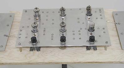
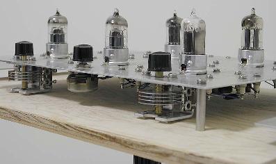
These are two photos of the 126 Theremin prototype, courtesy of Jack Hurwitz.
 |
 |
Johannes Graenzer of Bayreuth, Germany constructed this 126 Theremin
with monopole antennas for his university project. He reports that the
instrument worked "immediately... and sounds nearly as good as C.
Rockmore's if you play it by making a little vibrato..."

David Hunter of Toronto, Canada, built this 126 Theremin. The power
supply is in the base, along with a speaker and amplifier.

Christopher Billey submitted this picture of his 126 Theremin. His
version uses traditional antennas. It is his first vacuum tube
theremin, and he reports that he is "very pleased with pitch range and
sound quality." Christopher has more information about his theremin on
his webpage.

Brendan Pope, an 18 year-old student from North Carolina, built this
version of the 126 Theremin for his school project. It is the first
theremin he has ever owned or built. Brendon relates "Its sound is
supreme to any other homemade theremin I've heard."

Tomislav Ribicic of Croatia built this beautiful version of the 126
Theremin. The custom shellacked and waxed wood cabinet is topped by a
stainless steel chassis plate. Traditional rod and loop antennas were
used. Tomisalv reports that the theremin "sounds fabulous." He plans to
install the instrument in the Caffe Jazz Tunel in Rijeka.

Yaroslav Sadovskiy of Moscow, Russia built this amazing version of the 126 Theremin. The six vacuum tubes are illuminated by LEDs, and the legends, laser cut into stainless steel plate, are likewise illuminated. Yaroslav reports good pitch sensing distance with the telescoping antenna, which also serves to fine-tune the theremin's zero in lieu of vernier capacitors. The wood sides add a "touch of vintageness," per Yaroslav, who also reports that the 126 "has the pure, classic theremin sound." The author is very pleased to have this wonderful 126 created in the city where Leon Theremin worked for a decade at the Moscow Conservatory of Music.
|
|
|
|
|
|
Eric Reiswig from Canada built this
excellent 126 Theremin with traditional loop and rod antennas
fabricated from 3/8-inch diameter brass tubing. He incorporated the use
of an IC reversing circuit to permit optional "closer-for-softer"
volume response, and has expressed great satisfaction with the
instrument's sound qualities. Eric's work is documented on his theremin
webpage.
 |
 |
Jeremy Merrill constructed this beautiful 126 Theremin in a wormy chestnut cabinet with a stainless steel chassis inset. He reports that the tone is excellent, and that his success has inspired him to build additional vacuum tube projects. The antennas are copper tubing, and the stand was adapted from a lamp.
 |
 |
 |
| Table 1 | Theremin Assembly Schematic-designated Items |
| Table 2 | Power Supply Assembly Schematic-designated Items |
| Table 3 | Theremin Assembly Hardware Items |
| Table 4 | Power Supply Assembly Hardware Items |
| Table 5 | Base Assembly Items |
| Table 6 | Cable Assembly Items |
| Table 7 | Fixture Items |
Suppliers indicated are not necessarily exclusive sources.
Table 7 indicates temporary items used to aid construction.
A/R = as required
† = item appears on more than one line.
NOTE 1: One each, McMaster-Carr stock number 89015K37, provides enough material for both antennas.
NOTE 2: Obtain material locally, fabricate per drawing.
NOTE 3: The following manufacturers
make transformers similar to the Signal Transformer Company types
indicated in the table:
Triad Magnetics: http://www.triadmagnetics.com/home.htm.
Refer to their "Quick Pack" (TM) product line.
Magnetic Coils, Inc.: http://www.mcitransformer.com/.
Refer to their "Quick Connect Power Transformers" product line.
Hammond Manufacturing: http://www.hammondmfg.com/.
Refer to their "186/187" product line.
| LINE | ITEM | DESCRIPTION | VALUE | MANUFACTURER |
MANUFACTURER PART |
SUPPLIER | SUPPLIER STOCK NUMBER |
QTY |
| 101† | A1,A2 | ANTENNA (PER DRAWING) (SEE NOTE 1, ABOVE) |
. | . | . | MCMASTER-CARR | 89015K37 | 1 |
| 102 | C1, C12, C14, C20, C23 |
ELECTROLYTIC CAPACITOR |
10uF ±20%, 100V, 105°C, RADIAL, 6.3mm D x 11mm L |
NICHICON | UPW2A100MED | MOUSER ELECTRONICS |
647- UPW2A100MED |
5 |
| 103 | C2, C17, C26 |
MICA CAPACITOR |
330pF ±5%, 500V |
CORNELL DUBILIER |
CD19FD331JO3 | MOUSER ELECTRONICS |
5982- 19-500V330 |
3 |
| 104 | C3 | MICA CAPACITOR |
100pF ±5%, 500V |
CORNELL DUBILIER |
CD15FD101JO3 | MOUSER ELECTRONICS |
5982- 15-500V100 |
1 |
| 105 | C4, C15 | CERAMIC CAPACITOR |
330pF ±10%, X7R, 200V, RADIAL |
AVX | CK05BX331K | MOUSER ELECTRONICS |
581- CK05BX331K |
2 |
| 106 | C5, C24 | VARIABLE CAPACITOR |
6.2-27pF, 8:1 VERNIER |
HARRISON INSTRUMENTS |
99999- 5910-7-27R0 |
HARRISON INSTRUMENTS |
99999- 5910-7-27R0 |
2 |
| 107 | C6 | MICA CAPACITOR |
10pF ±5%, 500V |
CORNELL DUBILIER |
CD10CD100DO3 | MOUSER ELECTRONICS |
5982- 10-500V10 |
1 |
| 108 | C7, C8, C21, C22 |
CERAMIC CAPACITOR |
1000pF ±10%, X7R, 200V, RADIAL |
AVX | CK05BX102K | MOUSER ELECTRONICS |
581- CK05BX102K |
4 |
| 109 | C9, C10 C11, C13, C18, C19, C27, C28, C29 |
METALIZED POLYESTER CAPACITOR |
0.01uF
±5%, 400V, AXIAL |
VISHAY/ ROEDERSTEIN |
MKT1813310404 | MOUSER ELECTRONICS |
75- MKT1813310404 |
9 |
| 110 | C16, C25 | MICA CAPACITOR |
1000pF ±5%, 500V |
CORNELL DUBILIER |
CD19FD102JO3 | MOUSER ELECTRONICS |
5982- 19-500V1000 |
2 |
| 111† | J1 | CONNECTOR | 9 POSITION, MALE CONTACTS, D-SUBMINIATURE |
CINCH | DEH-9P | MOUSER ELECTRONICS |
538-DEH-9P | 1 |
| 112† | J2 | PHONE JACK, WITH HARDWARE | 1/4", INSULATED, MONOPHONIC |
SWITCHCRAFT | N111X | MOUSER ELECTRONICS |
502-N-111X | 1 |
| 113 | L1, L2, L3 |
INDUCTOR, THREE-SECTION, UNIVERSAL "PIE" WOUND |
1 mH ±5%, 19 OHM, Q = 59 @ 0.25MHz, SRF = 3.7MHz MINIMUM |
J.W. MILLER | 4652 | HARRISON INSTRUMENTS |
96804-4652 | 3 |
| 114 | R1, R13 R18, R23 |
RESISTOR | 5600 OHM ±5%, 1/2W, CARBON FILM |
XICON | 293-5.6K-RC | MOUSER ELECTRONICS |
293-5.6K-RC | 4 |
| 115 | R2 | RESISTOR | 33.2K OHM ±1%, ±100PPM/°C 1/4W, METAL FILM |
VISHAY / DALE | RN60D3322FB14 | MOUSER ELECTRONICS |
71-RN60D-F-33.2K | 1 |
| 116 | R3 | RESISTOR | 390K OHM ±5%, 1/2W, CARBON FILM |
XICON | 293-390K-RC | MOUSER ELECTRONICS |
293-390K-RC | 1 |
| 117 | R4, R5, R7, R8, R12, R15 R17, R25 |
RESISTOR | 1M OHM ±5%, 1/2W, CARBON FILM |
XICON | 293-1M-RC | MOUSER ELECTRONICS |
293-1M-RC | 8 |
| 118 | R6 | RESISTOR | 2000 OHM ±5%, 1/2W, CARBON FILM |
XICON | 293-2K-RC | MOUSER ELECTRONICS |
293-2K-RC | 1 |
| 119 | R9, R10, R11 | RESISTOR | 10K OHM ±5%, 1/2W, CARBON FILM |
XICON | 293-10K-RC | MOUSER ELECTRONICS |
293-10K-RC | 3 |
| 120 | R14, R24 | RESISTOR | 39.2K OHM ±1%, ±100PPM/°C 1/4W, METAL FILM |
VISHAY / DALE | RN60D3922FB14 | MOUSER ELECTRONICS |
71-RN60D-F-39.2K | 2 |
| 121 | R16, R26, R27 |
RESISTOR | 3900 OHM ±5%, 1/2W, CARBON FILM |
XICON | 293-3.9K-RC | MOUSER ELECTRONICS |
293-3.9K-RC | 3 |
| 122 | R19 | RESISTOR | 100K OHM ±5%, 1/2W, CARBON FILM |
XICON | 293-100K-RC | MOUSER ELECTRONICS |
293-100K-RC | 1 |
| 123 | R20, R21, R22 |
RESISTOR | 39K OHM ±5%, 1/2W, CARBON FILM |
XICON | 293-39K-RC | MOUSER ELECTRONICS |
293-39K-RC | 3 |
| 124 | R29 | RESISTOR | 18K OHM ±5%, 1/2W, CARBON FILM |
XICON | 293-18K-RC | MOUSER ELECTRONICS |
293-18K-RC | 1 |
| 125 | RV1 | POTENTIOMETER, WITH HARDWARE |
50K OHM ±20%, 0.25 WATT, CARBON COMPOSITION, AUDIO TAPER, WITH MOUNTING NUT AND FLAT WASHER |
ALPHA | RV24AF-10- 15R1-A50K-3 |
MOUSER ELECTRONICS |
31VJ405-F3 | 1 |
| 126 | V1, V2, V3 V4, V5, V6 |
VACUUM TUBE, DUAL TRIODE |
. | TESLA | ECC82 | ANTIQUE ELECTRONICS SUPPLY |
T-12AU7-JJ | 6 |
| 127 | X1 | CERAMIC FILTER | UNLOADED fo = 462kHz ±2kHz, 3dB BDW = 10kHz ±3kHz, RIPPLE = 0dB, MAX. INSERTION LOSS = 5dB Zin = 3kΩ Zout = 3KΩ |
MURATA SIGNAL CONDITIONING PRODUCTS |
SFULA455KU2A-B0 | HARRISON INSTRUMENTS |
99999-5915-126X1 | 1 |
| LINE | ITEM | DESCRIPTION | VALUE | MANUFACTURER | MANUFACTURER PART NUMBER | SUPPLIER | SUPPLIER STOCK NUMBER | QTY |
| 201 | BR1 | RECTIFIER BRIDGE | 6A, 200V |
RECTRON | BR62 | MOUSER ELECTRONICS |
583-BR62 | 1 |
| ^202 | C30, C31 | ELECTROLYTIC CAPACITOR | 330uF
±20%, 100V, 85°C, AXIAL, 13mm D x 31.5mm L |
NICHICON | TVX2A331MCD | MOUSER ELECTRONICS |
647-TVX2A331MCD | 2 |
| 203 | F1 | CARTRIDGE FUSE | 1/8A, 250V, SLOW-ACTING, 0.25" D x 1.25" L |
LITTELFUSE | 576-0313.125MXP | MOUSER ELECTRONICS |
576-0313.125MXP | 1 |
| 204† | J3 | CONNECTOR | 9 POSITION, FEMALE CONTACTS, D-SUBMIN- IATURE |
CINCH | DEH-9S | MOUSER ELECTRONICS |
538-DEH-9S | 1 |
| 205 | J4 | AC POWER INLET | 250VAC, 15A, CLASS 1 |
DGS PRO-AUDIO | 161-0707-1-E | MOUSER ELECTRONICS |
161-0707-1-E | 1 |
| 206 | R28 | RESISTOR | 100 OHM ±5%, 1/2W, CARBON FILM |
XICON | 293-100-RC | MOUSER ELECTRONICS |
293-100-RC | 1 |
| 207 | SW1 | SWITCH, TOGGLE, WITH HARDWARE |
6A, 250V, SPDT |
NKK | M2012SS1W01 | MOUSER ELECTRONICS |
633-M201201 | 1 |
| 208 | T1 | TRANSFORMER
(SEE NOTE 3, |
PRIMARY: 120V, 60Hz SECONDARY: 28V, 85mA |
SIGNAL TRANSFORMER COMPANY | 241-3-28 | SIGNAL TRANSFORMER COMPANY |
241-3-28 | 1 |
| 209 | T2 | TRANSFORMER
(SEE NOTE 3, |
PRIMARY: 120V, 60Hz SECONDARY: 10V, 1.2A |
SIGNAL TRANSFORMER COMPANY | 241-5-10 | SIGNAL TRANSFORMER COMPANY |
241-5-10 | 1 |
| LINE | ITEM | DESCRIPTION | MANUFACTURER |
MANUFACTURER PART |
SUPPLIER | SUPPLIER STOCK NUMBER |
QTY |
| 301† | THEREMIN MOUNTING PLATE | (PER DRAWING) | . | . | MCMASTER-CARR | 89015K37 | 1 |
| 302 | STANDOFF, THEREMIN MOUNTING PLATE | 6-32 x 1.25" L, HEXAGONAL, ALUMINUM |
KEYSTONE | 1818 | MOUSER ELECTRONICS |
534-1818 | 4 |
| 303 | MACHINE SCREW, STANDOFF, THEREMIN MOUNTING PLATE | PAN HEAD, SLOTTED, 6-32 x 0.375", STAINLESS STEEL |
. | . | MCMASTER-CARR | 91792A146 (PACKAGE OF 100) |
4 |
| 304† | FLAT WASHER, STANDOFF, THEREMIN MOUNTING PLATE | #6, 0.312" O.D., STAINLESS STEEL |
. | . | MCMASTER-CARR | 98019A314 (PACKAGE OF 500) |
4 |
| 305† | LOCK WASHER, STANDOFF, THEREMIN MOUNTING PLATE | #6 SPLIT-RING, 0.250" O.D., STAINLESS STEEL |
. | . | MCMASTER-CARR | 92146A540 (PACKAGE OF 100) |
4 |
| 306 | BRACKET, OUTPUT JACK | (PER DRAWING) | . | . | MCMASTER-CARR | 8199K13 | 1 |
| 307† | MACHINE SCREW, BRACKET, OUTPUT JACK | PAN HEAD, SLOTTED, 4-40 x 0.312", STAINLESS STEEL |
. | . | MCMASTER-CARR | 91792A107 (PACKAGE OF 100) |
2 |
| 308† | FLAT WASHER, BRACKET, OUTPUT JACK | #4, 0.250" O.D., STAINLESS STEEL |
. | . | MCMASTER-CARR | 98019A309 (PACKAGE OF 500) |
2 |
| 309† | LOCK WASHER, BRACKET, OUTPUT JACK | #4 SPLIT-RING, 0.209 O.D., STAINLESS STEEL |
. | . | MCMASTER-CARR | 92146A530 (PACKAGE OF 100) |
2 |
| 310† | NUT, BRACKET, OUTPUT JACK | HEX, 4-40 x 0.250", STAINLESS STEEL |
. | . | MCMASTER-CARR |
91841A005 (PACKAGE OF 100) |
2 |
| 311 | BRACKET, POWER CONNECTOR |
(MODIFIED PER DRAWING) |
KEYSTONE | 621 | MOUSER ELECTRONICS |
534-621 | 2 |
| 312† | MACHINE SCREW, BRACKET, POWER CONNECTOR | PAN HEAD, SLOTTED, 4-40 x 0.250", STAINLESS STEEL |
. | . | MCMASTER-CARR | 91792A106 (PACKAGE OF 100) |
2 |
| 313† | FLAT WASHER, BRACKET, POWER CONNECTOR | #4, 0.250" O.D., STAINLESS STEEL |
. | . | MCMASTER-CARR | 98019A309 (PACKAGE OF 500) |
2 |
| 314† | LOCK WASHER, BRACKET, POWER CONNECTOR | #4 SPLIT-RING, 0.209 O.D., STAINLESS STEEL |
. | . | MCMASTER-CARR | 92146A530 (PACKAGE OF 100) |
2 |
| 315† | JACK SCREW WITH HARDWARE, POWER CONNECTOR | 4-40, 0.250" L STUD |
KEYSTONE | . | MOUSER ELECTRONICS |
534-7229 |
2 |
| 316† | TERMINAL | INSULATED, SOLDER TURRET, 4-40 INTERNAL THREAD |
WEARNES CAMBION |
572-4814- 01-05-16 |
BISCO INDUSTRIES |
572-4814-01-05-16 | 49 |
| 317† | MACHINE SCREW, TERMINAL | PAN HEAD, SLOTTED, 4-40 x 0.250", STAINLESS STEEL |
. | . | MCMASTER-CARR | 91792A106 (PACKAGE OF 100) |
49 |
| 318† | FLAT WASHER, TERMINAL | #4, 0.250" O.D., STAINLESS STEEL |
. | . | MCMASTER-CARR | 98019A309 (PACKAGE OF 500) |
49 |
| 319† | LOCK WASHER, TERMINAL | #4 SPLIT-RING, 0.209 O.D., STAINLESS STEEL |
. | . | MCMASTER-CARR | 92146A530 (PACKAGE OF 100) |
49 |
| 320 | SOCKET, TUBE | 9-PIN, MINIATURE, WITH SHIELD RETAINER, 0.750" DIAMETER MTG HOLE, TOP-MOUNTED |
BELTON | VT-9-ST-C | TUBE DEPOT | SK-B-VT9-ST-C | 6 |
| ^321† | MACHINE SCREW, TUBE SOCKET | PAN HEAD, SLOTTED, 4-40 x 0.312", STAINLESS STEEL |
. | . | MCMASTER-CARR | 91792A107 (PACKAGE OF 100) |
12 |
| 322† | FLAT WASHER, TUBE SOCKET | #4, 0.250" O.D., STAINLESS STEEL |
. | . | MCMASTER-CARR | 98019A309 (PACKAGE OF 500) |
12 |
| 323† | LOCK WASHER, TUBE SOCKET | #4 SPLIT-RING, 0.209 O.D., STAINLESS STEEL |
. | . | MCMASTER-CARR | 92146A530 (PACKAGE OF 100) |
12 |
| 324† | NUT, TUBE SOCKET | HEX, 4-40 x 0.250", STAINLESS STEEL |
. | . | MCMASTER-CARR |
91841A005 (PACKAGE OF 100) |
12 |
| 325 | MACHINE SCREW, VARIABLE CAPACITOR | PAN HEAD, SLOTTED, 6-32 x 0.250", STAINLESS STEEL |
. | . | MCMASTER-CARR | 91792A144 (PACKAGE OF 100) |
4 |
| 326† | FLAT WASHER, VARIABLE CAPACITOR | #6, 0.312" O.D., STAINLESS STEEL |
. | . | MCMASTER-CARR | 98019A314 (PACKAGE OF 500) |
4 |
| 327† | LOCK WASHER, VARIABLE CAPACITOR | #6 SPLIT-RING, 0.250" O.D., STAINLESS STEEL |
. | . | MCMASTER-CARR | 92146A540 (PACKAGE OF 100) |
4 |
| 328 | KNOB, WITH SET SCREW | 25/32" D, 15/32" H, FOR 0.250" SHAFT, PHENOLIC, BLACK |
DAVIES | 1100 | MOUSER ELECTRONICS |
5164-1100 | 3 |
| 329† | LUG, GROUNDING | #4, INTERNAL TOOTH, 0.63" x 0.31" |
KEYSTONE | 908 | MOUSER ELECTRONICS |
534-908 | 1 |
| 330† | MACHINE SCREW, LUG, GROUNDING | PAN HEAD, SLOTTED, 4-40 x 0.250", STAINLESS STEEL |
. | . | MCMASTER-CARR | 91792A106 (PACKAGE OF 100) |
1 |
| 331† | FLAT WASHER, LUG, GROUNDING | #4, 0.250" O.D., STAINLESS STEEL |
. | . | MCMASTER-CARR | 98019A309 (PACKAGE OF 500) |
1 |
| 332† | NUT, LUG, GROUNDING | HEX, 4-40 x 0.250", STAINLESS STEEL |
. | . | MCMASTER-CARR |
91841A005 (PACKAGE OF 100) |
1 |
| 333† | WIRE, HOOKUP, DC RETURN | BLACK, 22 GAUGE, TEFLON® INSULATED, 100' ROLL |
WEICO WIRE | M16878/4BFE-0 | WEICO WIRE & CABLE | 2122/19-BLACK (ROLL OF 100') |
A/R |
| 334† | WIRE, HOOKUP, B+ | RED, 22 GAUGE, TEFLON® INSULATED, 100' ROLL |
WEICO WIRE | M16878/4BFE-2 | WEICO WIRE & CABLE | 2122/19-RED (ROLL OF 100') |
A/R |
| 335 | WIRE, HOOKUP, SIGNAL | BLUE, 22 GAUGE, TEFLON® INSULATED, 100' ROLL |
WEICO WIRE | M16878/4BFE-6 | WEICO WIRE & CABLE | 2122/19-BLUE (ROLL OF 100') |
A/R |
| 336† | WIRE, HOOKUP, HEATER | GRAY, 22 GAUGE, TEFLON® INSULATED, 100' ROLL |
WEICO WIRE | M16878/4BFE-8 | WEICO WIRE & CABLE | 2122/19-GRAY (ROLL OF 100') |
A/R |
| 337† | WIRE, BUS | 20 GAUGE, TINNED COPPER, 100' ROLL |
WEICO WIRE | 9020 | WEICO WIRE & CABLE | 9020 (ROLL OF 100') |
A/R |
| 338 | WIRE, BUS, ANTENNA LEAD-IN | 16 GAUGE, TINNED COPPER, 100' ROLL |
WEICO WIRE | 9016 | WEICO WIRE & CABLE | 9016 (ROLL OF 100') |
A/R |
| 339 | SLEEVING, INSULATION |
16 GAUGE, TEFLON®, 100' ROLL |
WEICO WIRE | TS-16 | WEICO WIRE & CABLE | TS-16 (ROLL OF 100') |
A/R |
| 340 | LUG, ANTENNA | #6, INTERNAL TOOTH, 0.63" x 0.31" |
KEYSTONE | 914 | MOUSER ELECTRONICS |
534-914 | 2 |
| 341 | WIRE TIE | NYLON, 3.9" L |
PANDUIT | PLT1M-C | MOUSER ELECTRONICS |
644-PLT1M-C | A/R |
| 342 | ANCHOR, WIRE TIE | NYLON, 1/2" SQ |
PANDUIT | ABM1M-A-M | MOUSER ELECTRONICS |
644-ABM1M-A-M | A/R |
| LINE | ITEM | DESCRIPTION | MANUFACTURER |
MANUFACTURER PART |
SUPPLIER | SUPPLIER STOCK NUMBER |
QTY |
| 401† | POWER
SUPPLY MOUNTING PLATE |
(PER DRAWING) | . | . | MCMASTER-CARR | 89015K37 | 1 |
| 402 | UTILITY CABINET, POWER SUPPLY, WITH HARDWARE |
2-PANEL, ALUMINUM, 5" x 6" x 4" |
BUD INDUSTRIES | AU-1029 | MOUSER ELECTRONICS |
563-AU-1029NF | 1 |
| 403 | FOOT, UTILITY CABINET | 0.81" SQ x 0.3" H, SELF ADHESIVE, GRAY |
3M | SJ-5023GY | MOUSER ELECTRONICS |
517-SJ-5023GY | 4 |
| 404 | MACHINE SCREW, AC POWER INLET MOUNTING |
FLAT HEAD, SLOTTED, 4-40 x 0.375", STAINLESS STEEL |
. | . | MCMASTER-CARR | 91781A108 FLAT HEAD (PACKAGE OF 100) |
2 |
| 405† | NUT, AC POWER INLET MOUNTING |
HEX, 4-40 X 0.250", STAINLESS STEEL |
. | . | MCMASTER-CARR | 91841A005 (PACKAGE OF 100) |
2 |
| 406† | FLAT WASHER, AC POWER INLET MOUNTING |
#4, 0.250" 0.D., STAINLESS STEEL |
. | . | MCMASTER-CARR | 98019A309 (PACKAGE OF 500) |
2 |
| 407† | LOCK WASHER, AC POWER INLET MOUNTING |
#4 SPLIT-RING, 0.209" O.D., STAINLESS STEEL |
. | . | MCMASTER-CARR | 92146A530 (PACKAGE OF 100) |
2 |
| 408† | LUG, GROUND | #4, INTERNAL TOOTH, 0.63" x 0.31" |
KEYSTONE | 908 | MOUSER ELECTRONICS |
534-908 | 1 |
| 409† | MACHINE SCREW, LUG, GROUND | PAN HEAD, SLOTTED, 4-40 x 0.250", STAINLESS STEEL |
. | . | MCMASTER-CARR | 91792A106 (PACKAGE OF 100) |
1 |
| 410† | FLAT WASHER, LUG, GROUND | #4, 0.250" O.D., STAINLESS STEEL |
. | . | MCMASTER-CARR | 98019A309 (PACKAGE OF 500) |
1 |
| 411† | NUT, LUG, GROUND | HEX, 4-40 x 0.250", STAINLESS STEEL |
. | . | MCMASTER-CARR | 91841A005 (PACKAGE OF 100) |
1 |
| 412† | MACHINE SCREW, TRANSFORMER | PAN HEAD, SLOTTED, 6-32 x 0.437", STAINLESS STEEL |
. | . | MCMASTER-CARR | 91792A147 (PACKAGE OF 100) |
4 |
| 413† | FLAT WASHER, TRANSFORMER | #6, 0.312 O.D., STAINLESS STEEL |
. | . | MCMASTER-CARR | 98019A314 (PACKAGE OF 100) |
4 |
| 414† | LOCK WASHER, TRANSFORMER | #6 SPLIT-RING, 0.250" O.D., STAINLESS STEEL | . | . | MCMASTER-CARR | 92146A540 (PACKAGE OF 100) |
4 |
| 415† | NUT, TRANSFORMER | HEX, 6-32 x 0.250", SMALL PATTERN, STAINLESS STEEL |
. | . | MCMASTER-CARR | 90730A007 (PACKAGE OF 100) |
4 |
| 416† | MACHINE SCREW, BRIDGE RECTIFIER |
PAN HEAD, SLOTTED, 6-32 x 0.437", STAINLESS STEEL |
. | . | MCMASTER-CARR | 91792A147 (PACKAGE OF 100) |
1 |
| 417† | FLAT WASHER, BRIDGE RECTIFIER |
#6, 0.312" 0.D., STAINLESS STEEL |
. | . | MCMASTER-CARR | 98019A314 (PACKAGE OF 500) |
1 |
| 418† | LOCK WASHER, BRIDGE RECTIFIER |
#6 SPLIT-RING, 0.250" O.D., STAINLESS STEEL |
. | . | MCMASTER-CARR | 92146A540 (PACKAGE OF 100) |
1 |
| 419† | NUT, BRIDGE RECTIFIER |
HEX, 6-32 x 0.250", SMALL PATTERN STAINLESS STEEL, |
. | . | MCMASTER-CARR | 90730A007 (PACKAGE OF 100) |
1 |
| 420† | TERMINAL | INSULATED, SOLDER TURRET, 4-40 INTERNAL THREAD |
WEARNES CAMBION |
572-4814- 01-05-16 |
BISCO INDUSTRIES |
572-4814-01-05-16 | 4 |
| 421† | MACHINE SCREW, TERMINAL |
PAN HEAD, SLOTTED, 4-40 x 0.250", STAINLESS STEEL |
. | . | MCMASTER-CARR | 91792A106 (PACKAGE OF 100) |
4 |
| 422† | FLAT WASHER, TERMINAL |
#4, 0.250" O.D., STAINLESS STEEL |
. | . | MCMASTER-CARR | 98019A309 (PACKAGE OF 500) |
4 |
| 423† | LOCK WASHER, TERMINAL |
#4 SPLIT-RING, 0.209 O.D., STAINLESS STEEL |
. | . | MCMASTER-CARR | 92146A530 (PACKAGE OF 100) |
4 |
| 424† | JACK SCREW WITH HARDWARE, POWER CONNECTOR | 4-40, 0.250" L STUD |
KEYSTONE | 7229 | MOUSER ELECTRONICS |
534-7229 | 2 |
| 425† | WIRE, HOOKUP, TRANSFORMER PRIMARY LINE | BLACK, 22 GAUGE, TEFLON® INSULATED, 100' ROLL |
WEICO WIRE | M16878/4BFE-0 | WEICO WIRE & CABLE | 2122/19-BLACK (ROLL OF 100') |
A/R |
| 426† | WIRE, HOOKUP, B+ | RED, 22 GAUGE, TEFLON® INSULATED, 100' ROLL |
WEICO WIRE | M16878/4BFE-2 | WEICO WIRE & CABLE | 2122/19-RED (ROLL OF 100') |
A/R |
| 427 | WIRE, HOOKUP, B+ TRANSFORMER SECONDARY |
YELLOW, 22 GAUGE, TEFLON® INSULATED, 100' ROLL |
WEICO WIRE | M16878/4BFE-4 | WEICO WIRE & CABLE | 2122/19-YELLOW (ROLL OF 100') |
A/R |
| 428 | WIRE, HOOKUP, SAFETY GROUND |
GREEN, 22 GAUGE, TEFLON® INSULATED, 100' ROLL |
WEICO WIRE | M16878/4BFE-5 | WEICO WIRE & CABLE | 2122/19-GREEN (ROLL OF 100') |
A/R |
| 429† | WIRE, HOOKUP, HEATER TRANSFORMER SECONDARY |
GRAY, 22 GAUGE, TEFLON® INSULATED, 100' ROLL |
WEICO WIRE | M16878/4BFE-8 | WEICO WIRE & CABLE | 2122/19-GRAY (ROLL OF 100') |
A/R |
| 430 | WIRE, HOOKUP, TRANSFORMER PRIMARY NEUTRAL |
WHITE, 22 GAUGE, TEFLON® INSULATED, 100' ROLL |
WEICO WIRE | M16878/4BFE-9 | WEICO WIRE & CABLE | 2122/19-WHITE (ROLL OF 100') |
A/R |
| 431† | WIRE, BUS | 20 GAUGE, TINNED COPPER, 100' ROLL |
WEICO WIRE | 297 SV005 | WEICO WIRE & CABLE | 602-297-100 | A/R |
| 432 | TUBING, HEAT-SHRINKABLE |
POLYOLEFIN, BLACK, 0.125"O.D., 48" |
3M | FP301 1/8 BLACK | MOUSER ELECTRONICS |
5174-1181 | A/R |
| 433 | TUBING, HEAT-SHRINKABLE |
POLYOLEFIN, BLACK, 0.250"O.D., 48" |
3M | FP301 1/4 BLACK | MOUSER ELECTRONICS |
5174-1141 | A/R |
| 434 | TUBING, HEAT-SHRINKABLE |
POLYOLEFIN, BLACK, 0.500"O.D., 48" |
3M | FP301 1/2 BLACK | MOUSER ELECTRONICS |
5174-1121 | A/R |
| LINE | ITEM | DESCRIPTION | MANUFACTURER |
MANUFACTURER PART |
SUPPLIER | SUPPLIER STOCK NUMBER |
QTY |
| 501 | BASE | (SEE NOTE 2, ABOVE) |
. | . | . | . | 1 |
| 502 | STANDOFF, ANTENNA |
6-32 x 0.500 L, HEXAGONAL, NYLON |
KEYSTONE | 1903C | MOUSER ELECTRONICS |
534-1903C | 8 |
| 503† | MACHINE SCREW, ANTENNA |
PAN HEAD, SLOTTED, 6-32 x 0.312", STAINLESS STEEL |
. | . | MCMASTER-CARR | 91792A145 (PACKAGE 0F 100) |
8 |
| 504† | FLAT WASHER, ANTENNA |
#6, 0.312" O.D., STAINLESS STEEL |
. | . | MCMASTER-CARR | 98019A314 (PACKAGE OF 500) |
8 |
| 505† | LOCK WASHER, ANTENNA |
#6 SPLIT-RING, 0.250" O.D., STAINLESS STEEL |
. | . | MCMASTER-CARR | 92146A540 (PACKAGE OF 100) |
8 |
| 506 | MACHINE SCREW, BASE |
FLAT HEAD, SLOTTED, 6-32 x 0.625", STAINLESS STEEL |
. | . | MCMASTER-CARR | 91781A150 FLAT HEAD (PACKAGE OF 100) |
12 |
| 507 | ADAPTER, MICROPHONE STAND |
1.75" O.D., 0.71" H, 5/8-27 INTERNAL THREAD |
ATLAS SOUND | AD-11B | HARRISON INSTRUMENTS |
99999-AD-11B | 1 |
| 508 | THREAD-FORMING SCREW, ADAPTER |
PAN HEAD, TYPE A, PHILLIPS, #6 X 1/2", STAINLESS STEEL |
. | . | MCMASTER-CARR | 92470A148 (PACKAGE OF 100) |
3 |
| LINE | ITEM | DESCRIPTION | VALUE | MANUFACTURER |
MANUFACTURER PART |
SUPPLIER | SUPPLIER STOCK NUMBER |
QTY |
| 601 | . | CABLE, 4-CONDUCTOR |
4 22-GAUGE, 7 x 30 STRAND TINNED COPPER CONDUCTORS, PVC INSULATED, PVC JACKET, 0.185" O.D. |
BELDEN | 8444 | MOUSER ELECTRONICS |
566-8444-100 (ROLL OF 100') |
A/R |
| 602† | P1 | CONNECTOR, 4-CONDUCTOR CABLE |
9 POSITION, MALE CONTACTS, D-SUBMINIATURE |
CINCH | DEH-9P | MOUSER ELECTRONICS |
538-DEH-9P | A/R |
| 603† | P2 | CONNECTOR, 4-CONDUCTOR CABLE |
9 POSITION, FEMALE CONTACTS, D-SUBMINIATURE |
CINCH | DEH-9S | MOUSER ELECTRONICS |
538-DEH-9S | 1 |
| 604 | . | MALE SCREW LOCK WITH "U" CLIP, CONNECTOR |
4-40, 0.250" L |
TYCO/AMP | 5205980-1 | MOUSER ELECTRONICS |
571-5205980-1 | 2 |
| 605 | . | HOOD, CONNECTOR |
. | TYCO/AMP | 207467-1 | MOUSER ELECTRONICS |
571-2074671 | 2 |
| 606 | . | CORD, POWER |
3 18-GAUGE, 41 x 34 STRAND CONDUCTORS, SVT JACKET, 10' L, SHIELDED |
KOBICONN | 173-0621-E | MOUSER ELECTRONICS |
173-0621-E | 1 |
| LINE | ITEM | DESCRIPTION | VALUE | MANUFACTURER |
MANUFACTURER PART |
SUPPLIER | SUPPLIER STOCK NUMBER |
QTY |
| 701 | STANDOFF | 6-32 x 2.5" L, HEXAGONAL, ALUMINUM |
. | KEYSTONE | 1825 | MOUSER ELECTRONICS |
534-1825 | 4 |
| 702 | STANDOFF | 6-32 x 2.0"L, HEXAGONAL, MALE/FEMALE, ALUMINUM |
. | KEYSTONE | 8425 | MOUSER ELECTRONICS |
534-8425 | 4 |
Drawing
Index
(back
to contents)
| Schematic (page 1), with Volume Response Switch |
Text and drawings ©2002, 2003, 2005, 2008, 2010, 2013, 2014 by Arthur
Harrison
Contact Author


