LED SEQUENCER
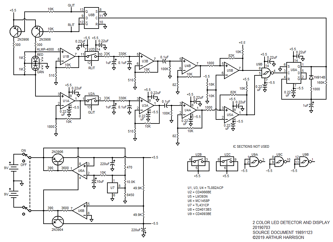
Although intended as an illumination source, LEDs also produce a small current when illuminated, making them suitable as light detectors. This unusual circuit uses a single-packaged dual LED which contains one red and one green die. While one LED is illuminated, the other is used as an ambient light detector. Under typical conditions, interrupting the ambient light to the LED package will cause the circuit to turn off the LED that was initially on, and turn on the LED that was initially off. Waving your hand over the LED package in repetition, therefore, causes the illumination color to alternate between red and green.
Flip-flop U8B drives current via PNP transistors through either the red or green die while in their illuminating modes. While in their detection modes, initial gain is provided by U1B for the red LED die and U1A for the green LED die. The gain and control chains for each LED die are identical, with the exception of a front-end gain of 30.5 provided for the red LED die, compared with a gain of 5.55 for the green LED die.
While the red LED die is on, switch U2D is held open, and U2A is held closed, allowing the green LED die's photo current to be further-amplified by U3A and U4A. A two-pole low-pass filter preceding the U3A amplifier rejects the 60 Hz AC signal component caused by typical room lighting. Note that the DC offset term is eliminated between amplifiers U3A and U4A by means of AC coupling.
Comparator U5A's output goes to a low logic level when the amplitude of the signal at U4A's output falls below the reference voltage established by the 18K-10K voltage divider. Such a drop in amplitude correlates with a reduction of ambient light on the green LED die, caused by the shadow of the object being detected. The low logic level is applied to pin 9 of NAND gate U9B. Given that U9B's input pin 6 is high, pin 4 goes high, triggering a monostable multivibrator comprised of flip-flop U8A and associated components. A high-going pulse is applied from U8A's Q output to the input of toggle flip-flop U8B, causing it to change state, removing current from the green LED, and illuminating the red LED, instead. Now, the green LED performs as the detector, and its associated signal chain causes U8A to trigger when the amplitude of the signal at U4B's output again falls below the reference voltage.
Operational amplifier U6, voltage reference U7, and associated components, form a ±5.5 volt tracking regulator to provide power to the circuit from two 9-volt batteries.

July 3, 2019
Text and images ©2019 by Arthur Harrison
Back to the Circuit Library Index
Back to the Opening Page of Art's Theremin Page