Pseudorandom-Sequential Ring-Modulated Tone Generator
NOTICE: Unless specifically stated in a written
contract, Arthur Harrison grants no licence to any party for the use of the
content |
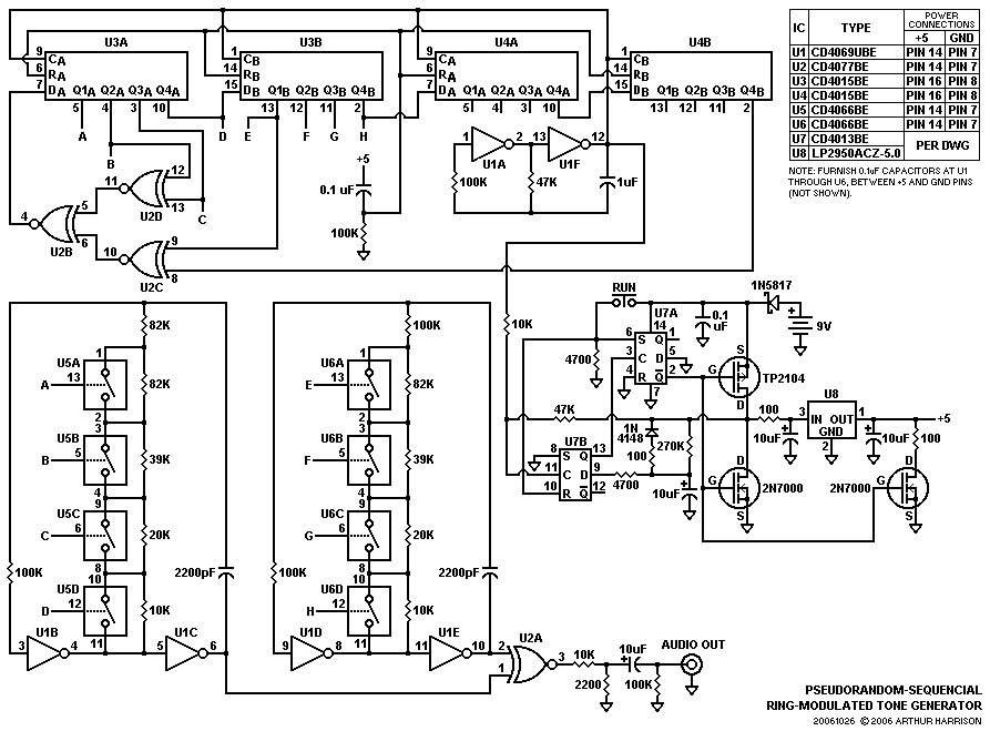
The circuit illustrated produces a short duration of rapidly-sequencing tones, invoking the stereotypical sonic imagery of a sophisticated computer, such as would be scripted for the science-fiction genre. I designed this circuit for use in the composition "Be Quite Still," by the popular band, "The Cassettes." A similar riff had been provided by a Moog Rogue analog synthesizer for the band's studio recording, but dedicating the synthesizer to just this brief effect, alone, would have prevented its use for other parts of the composition in live peformances.
The circuit is comprised of a 16-bit serial shift register (U3 and U4), clocked by multivibrator U1A-U1F, and employing data feedback via three exclusive-nor gates, U2B,C, and D. This implements a digital word generator that propagates pseudorandom data through the register, of which the first four bits are used to control the frequency of an audio oscillator, comprised of inverters U1B-U1C and quad analog switch U5. Similarly, bits 5 through 8 control a second audio oscillator, comprised of U1D-U1E and U6. The two squarewave oscillator outputs are fed to exclusive-nor gate U2A, which combines them in a manner similar to a ring-connected diode mixer, producing sum and difference frequencies of the two squarewaves, resulting in harmonically-complex tones at the AUDIO OUT jack.
Flip-flops U7A and U7B, voltage regulator U8, and associated components form a power-control circuit that provides voltage to the tone generator for a duration of about two seconds. The duration is adjustable by varying the 270K resistor. U7B ensures that the circuit turns off after the last tone is completed, thus preventing the annoyance of a short interval at the end of the effect. To provide a large variety of tone pairs, the two squarewave oscillators are offset in frequency by using an 82K resistor in one, and a 100K resistor in the other. A momentary closure of the RUN switch will initiate a two-second sequence. If the switch is held closed for a longer period, the sequence will continue while the switch is held, and end as soon as the switch is released. Given the considerable length of the generated code (2^16 words), and the 256 possible squarewave pairs, the circuit will produce an extremely long sequence before repeating.
The use of CMOS devices in the power control section eliminates the need for an on-off switch, since standby current is essentially zero. The circuit consumes less than 3 milliamperes while operating, providing extensive battery life. The 1N5817 Schottky rectifier prevents damage to the CMOS devices in the event of accidental battery reversal. In constructing this circuit, it is recommended that the U1 inverter sections "A" through "F" are allocated exactly as shown, since rearranging the otherwise-identical sections may cause sufficient coupling between the two audio oscillators for phase-locking, evident as "dead" tone intervals. Click here for an audio sample of this circuit's output.

October 26, 2006
Text and images ©2006 by Arthur Harrison
Back to the Circuit Library Index
Back to the Opening Page of Art's Theremin Page