 |
TELEPHONE OFF-HOOK TONE GENERATOR
This circuit generates the sound that many telephone companies use to attract the customer's attention to their phone when they leave it "off hook." It is also refered to, in telephony jargon, as "ROH," for "receiver off-hook."
The sound is comprised of four sine waveforms, added in equal proportions, and keyed on and off at a rate of 5 Hertz. In practice, the sequence is usually administered in two 50-second servings, preceded by a recorded announcement requesting that the phone be put back on its hook.
Circuit operation is as follows: Referring to page 1 of the schematic, operational amplifier U1A and associated components form an oscillator that produces a 1400Hz triangle-like waveform at U1A's negative input. The waveform is connected to analog switch U4A, which is controlled by a 5Hz, 50 percent duty cycle square wave designated "EN" (enable). When "EN" is at a logic "high" level, U4A is closed, and the 1400Hz signal is applied to the input of a unity-gain impedance buffer, operational amplifier U6A. A second analog switch, U4B, is controlled by "INH" (inhibit), which is logically high when "EN" is logically low. This switch shunts any leakage signal at U4's output to ground while U4A is is open. The complimentary "EN" and "INH" square waves are generated by operational amplifiers U7A and B, shown on page 3 of the schematic.
U6A's output is connected to a Sallen-Key low-pass filter comprised of operational amplifier U9A and associated components. This filter converts the 1400Hz triangle-like waveform at U6A's output into a sine wave. In addition, the filter removes "clicks" caused by the rapid on-off transition of the "EN" and "INH" signals. Note that impedance buffer U6A isolates oscillator U1's frequency-determining components from the filter.
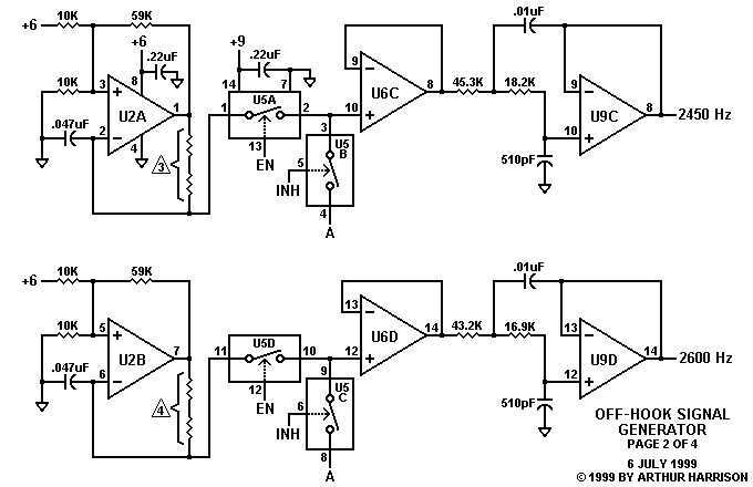
Three additional sections, each consisting of a tone oscillator, two keying switches, buffer, and filter, provide keyed signals of 2260Hz (schematic page 1), 2450Hz, and 2600Hz (schematic page 2). The four keyed tones are summed at the negative input of operational amplifier U8B that, with its associated components, form an output amplifier capable of driving a small speaker such as the 100 ohm unit indicated in the schematic, or the unit commonly used in telephone handsets.
To ensure frequency stability with battery variations, the five oscillators are supplied by 6V regulator U3 and associated components, shown on page 3. The circuit draws about 10mA from a 9V battery. The fuse and rectifier at the regulator's input provide protection from battery reversal. An audio example from this circuit is provided here.
 |
 |
 |

July 11, 1999 Text and images ©1999 by Arthur Harrison Source documents dated July 9, 1991
Back to the Circuit Library Index Back to the Opening Page of Art's Theremin Page |