 |
PHONE LINE IN-USE INDICATORS
Presented are two different designs that perform the same function. Each circuit lights an LED when a telephone line is in use, and can be placed at extension telephones to alert others not to interrupt. Unlike "off-hook" indicator circuits, these circuits do not have to be inserted in series with the telephone; they are simply plugged into the telephone line to provide an indication that one or more of the phones on that line are being used. Both circuits are powered by 9v batteries, and therefore present little danger of imposing an unsafe condition on the telephone line or equipment.
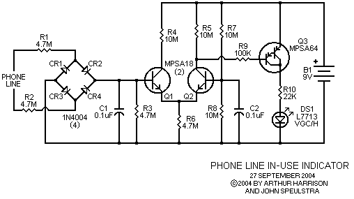
The first circuit, shown in Figure 1, uses discrete components. Its current
drain is minimal (about 1 microampere with the LED off and 0.3 milliampere
with the LED on), providing long battery life. This extremely low-power operation
is achieved by the use of high-beta transistors and a high-efficiency
LED.
 |
Operation is as follows: The telephone line voltage is applied to a
full-wave bridge rectifier, comprised of diodes CR1 through CR4. The bridge
ensures that the voltage is positive with respect to the circuit's ground.
A differential pair consisting of transistors Q1 and Q2 and resistors R4,
R5 and R6 compares the line voltage, applied to Q1's base via R1 and R2,
to a reference voltage, applied to Q2's base via R7 and R8. When one or more
telephones on the line is off-hook, the telephone line voltage drops to about
7 volts, providing about 2.2 volts to the base of Q1. In this condition,
Q1 is cut off and Q2 turns on, providing base current to Darlington transistor
Q3. Q3 turns on, illuminating the LED.
When all the telephones are on-hook, approximately 48 volts appears across the line. In this condition, the voltage at Q1's base is greater than the reference voltage at Q2's base, turning Q1 on and cutting Q2 off. Q3, in turn, is cut off, extinguishing the LED. Resistors R1 and R2 form a voltage divider in conjunction with R3 to scale the bridge's output voltage to a range useful to the comparitor. While R1 and R2 are electrically equivalent to a single 9.4M ohm resistor, this resistance is intentionally split into two parts so that a high resistance is physically present at both phone line inputs. Provided that each resistor is located close to the circuit's input points, the chances of an unintended short-circuit from either input to another point in the circuit is therefore minimized.
Capacitors C1 and C2 provide noise suppression, and resistor R10 limits the LED current. The circuit changes state at approximately 20 volts when used with a fresh 9v battery, and has sufficient tolerance to operate correctly for the battery's useful life.
 |
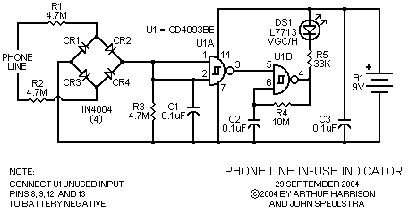
Another circuit, shown above in Figure 2, uses an integrated circuit, and provides the additional feature of blinking the LED on and off, which extends battery life. Also, this version of the circuit has no measurable standby current, as long as the on-hook line voltage is greater than approximately 25 volts. The average current drain while the LED is blinking is about 0.15 milliampere.
Operation is as follows: As in the first circuit, telephone line voltage is applied to a full-wave bridge rectifier, comprised of diodes CR1 through CR4, ensuring that the voltage is positive with respect to the circuit's ground. The voltage is applied to the input of U1A, a 2-input NAND Schmitt trigger connected as an inverter. The Schmitt trigger's inherent transfer function causes its output to be in a low state whenever its input voltage is greater than approximately half of its supply voltage of 9 volts. Conversely, a voltage input lower than half of its supply voltage will cause U1A's output to be in a high state. When one or more telephones is off-hook, the line voltage drops to about 7 volts, providing about 2.3 volts to U1A's input, resulting in a high state at its output. In this condition, 2-input NAND Schmitt trigger U2B, configured as a relaxation oscillator, is enabled, causing the LED to flash at about 2.5 Hertz, as determined by capacitor C2 and resistor R4.
Hysteresis, inherently part of the Schmitt triggers and U1A in particular, causes the voltage threshold to differ from LED-flashing to LED-off states. For a telephone line voltage increasing from zero, the LED turns off at approximately 20 volts. For a telephone line voltage decreasing from its maximum value (48 volts) toward zero volts, the LED begins flashing at approximately 15 volts. This hysteretic effect is advantageous in providing immunity to spurious line voltage transients.
Current limiting and scaling of the line voltage is provided by R1, R2, and R3. As in the first circuit, splitting the input resistance into two resistors reduces the chances of an unintended short-circuit from either input to another point in the circuit. Capacitor C1 provides noise suppression, and C3 provides power supply decoupling for U1. Note that two of the four NAND Schmitt sections are unused, and that their inputs must be grounded. Alternatively, these two sections may be used for a second line indicator. It must be emphasized that a high-efficiency LED such as the Kingbright type L7713VGC/H must be used in these circuits, since the small currents provided will not sufficiently illuminate standard LEDs.
WARNING ! Under no circumstances may a user connect this or any other non-approved device to a telephone line without obtaining specific, prior permission from their telephone company. Under no circumstances may any external voltage be connected to telephone lines. The diode bridge in this circuit provides isolation between the telephone line and user-defined circuitry to satisfy this requirement. The 9v battery provides isolation from mains power circuits to prevent shock hazards in the event of a voltage surge from lightning or other abnormal conditions. Do not defeat either of these provisions. |
September 27, 2004
Text and images ©2004 by Arthur Harrison and John Speulstra
Back to the Circuit Library Index
Back to the Opening Page of Art's Theremin Page