 |
SINGLE-SUPPLY DIFFERENTIAL-PAIR L-C OSCILLATOR
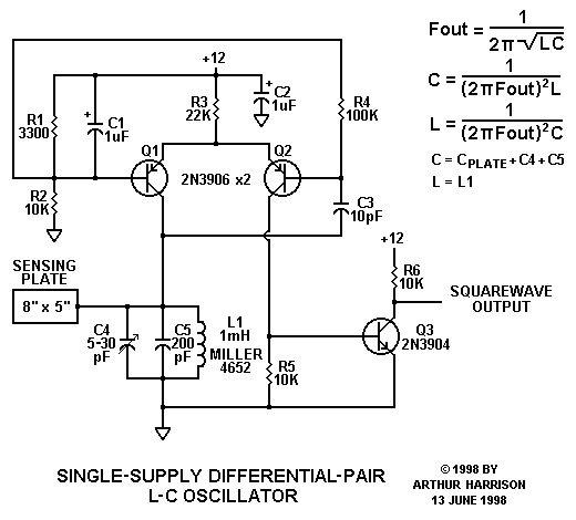
This oscillator uses a differential transistor pair, Q1 and Q2, to control the current in a parallel-resonant tank consisting of L1, C4, and C5. Upon power application, Q1 supplies current to the tank, causing it to ring at resonance. Part of the ringing voltage is coupled to Q2's base via C3. Q2 conducts, turning Q1 off. The voltage at Q1's collector continues to change as a result of resonance, turning Q2 off, and again allowing Q1 to conduct.
Although current applied to the tank is non-continuous, the tank's inherently high Q factor preserves the sinusoidal voltage waveform at its resonant frequency. Transistor Q3 provides voltage gain, as well as impedance isolation, preventing subsequent stages from loading the tank. R1 and R2 form a voltage divider that biases Q1's base. This bias is also provided to Q2's base via R4. C1 decouples Q1's base from the AC component resulting from the waveform present at Q2's base. R3 sets the current, and thus the gain, of the differential pair. R5 sets the collector voltage swing at Q2, biasing Q3 for an approximate 50 percent duty cycle waveform at its collector.
The inclusion of a sensing plate in the tank circuit illustrates the application of this circuit as a theremin detector. Indeed, the circuit topology is very similar to the variable oscillator utilized in a popular commercial theremin, with the exception that it has been modified for single-supply operation, and that the use of a PNP differential pair affords a grounded tank, allowing a grounded-rotor variable tuning capacitor (C4). This provides the dual benefits of permitting the variable capacitor to be chassis-mounted, and also preventing a frequency shift when the tuning capacitor is touched. (Alternatively, as in many heterodyne theremin topologies, the tuning capacitor may be incorporated in the fixed-frequency oscillator, as opposed to the variable oscillator, as shown.) The squarewave output furnished by Q3 is useful in many applications, although a good quality sinewave can also be obtained from the collector of Q1. This point, however, should be buffered from subsequent stages with a field-effect transistor source follower that exhibits minimal loading.
This circuit exhibits excellent frequency stability over temperature, making it a good choice for heterodyne theremins. For optimal temperature independence, C4 should be an air-variable type, and C5 should be mica. C3 may be an C0G ceramic or mica type. L1 is a three section "pie" wound, phenolic core type with negligible temperature drift. The resistors may be 5 percent tolerance carbon film types, or nearest-value 1 percent metal film types.
Discounting parasitic circuit reactances, the oscillator's nominal frequency is approximately equal to 1/2pi[sq.rt.L1(C4+C5+Csensing plate)]. The 8" x 5" sensing plate exhibits a capacitance of about 10 picofarads to free space. Typically, the hand will add about 2 picofarads of additional tank capacitance when positioned parallel to the plate at a distance of two inches. For L1=1mH and Ctotal=230pF, the output frequency is about 331.86 kiloHertz. An additional 2 picofarad hand capacitance will decrease the frequency about 1400 Hertz. The circuit exhibits an average power-supply voltage sensitivity of about 160 Hertz per volt, and will operate from as little as 8 volts. Since some power supply sensitivity is indicated, the 12 volt supply should be regulated.
 |
June 13, 1998
Text and images ©1998 by Arthur Harrison
Back to the Circuit Library Index
Back to the Opening Page of Art's Theremin Page