 |
SQUARE WAVE TO TRIANGLE WAVE CONVERTER
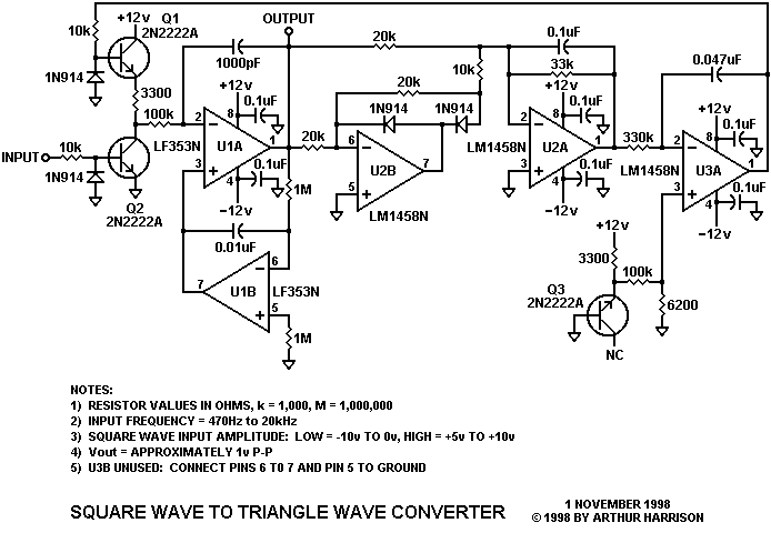
This circuit converts a square waveform to a triangle waveform while automatically maintaining a constant triangle amplitude for a wide range of input frequencies. Although originally designed for application in a communications system, the idea is readily adaptable for certain electronic music applications where waveform conversion is desired.
Operation is as follows: Transistor Q2 provides a square wave at its collector that has an amplitude controlled by Q1. The square wave is fed to an integrator consisting of operational amplifier U1A and associated components. Operational amplifier U1B integrates U1A's output, compares it to ground, and provides a term at U1A's positive input that maintains U1A's output centered about ground. Operational amplifiers U2A and U2B and associated components comprise a full-wave precision rectifier and averaging circuit. The DC value developed at U2A's output is fed to an integrating servo amplifier consisting of U3A and associated components. The servo amplifier's reference is obtained from reverse-biased transistor Q3 and its voltage divider. The servo's output is an error term which corresponds to the input waveform's frequency, and is fed to the base of transistor Q1, causing the amplitude of the square wave at Q2's collector to adjust to a value that maintains a voltage at U2A's output equal to the servo's reference value.
It should be noted that the amplitude adjustment response for this circuit is not instantaneous, although appropriate selection of the integrating and averaging capacitor values will minimize amplitude shifts during frequency excursions. Abrupt changes in the input frequency will result in prolonged settling times that may render the circuit unsuitable for certain music applications. Response may possibly be improved with a more complex servo amplifier that adds proportional and derivative terms to the integral term.
When connected to a theremin with a square wave output of constant amplitude, (the capacitor values having been optimized for the bandwidth of interest), this circuit produced an interesting effect in which frequency transitions caused a gentle frequency-transition-dependent modulation of the triangle output amplitude, reminiscent of the amplitude modulations performed by utilizing the "swell" pedal on a pipe organ. This automatic crescendo and decrescendo added depth to the theremin's quality.
This circuit's input is not restricted to square waves; a 5 percent duty-factor rectangular wave input, for example, will result in a sawtooth, as opposed to a triangular output.
Acknowledgement
The author gratefully acknowledges Rick Hansen for the design concepts incorporated in this circuit.
 |
November 1, 1998
Text and images ©1998 by Arthur Harrison
Source documents dated circa 1985
Back to the Circuit Library Index
Back to the Opening Page of Art's Theremin Page