 |
ALTERNATING TWO LED FLASHER
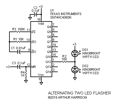
This is a simple circuit that illuminates two LEDs alternately. It is useful, for example, in model railroad crossing displays and warning indicators, among other applications.
The circuit offers these features:
Referring to the schematic, U1 is a 14-stage asynchronous binary counter with its first stage internally connected to its internal clock. The clock frequency is set with the values of R1 and C1, in this case, for approximately 4.55 kHz, as determined by the equation f = 0.455 / R1 C1. That frequency is divided by 212 (4096) at the Q12 output, providing an LED alternation frequency of about 1.11 Hz, which illuminates each LED for about 0.45 s. When the Q11 output is logically "low," current flows through resistor R2 and LED DS1 to the positive supply, exclusively illuminating DS1. Conversely, when the output is logically "high," current flows through R2 and DS2 to ground, exclusively illuminating DS2.
R2 is selected so that the LED currents are around 10 mA. R2's value should be greater than zero, since the LED currents would otherwise be limited only by the "on" resistances of U1s MOS output transistors. To ensure proper operation and good power efficiency, the supply voltage should be just high enough to adequately illuminate the LEDs. The minimum circuit voltage is 2 V, and the maximum is 6 V, determined by the IC specifications.
The Kingbright WP7113SRD/J4
LEDs specified in the schematic are red-emitting Aluminum Gallium
Indium Phosphide diffuse types with a 1800 mcd typical luminous
intensity (@20 mA), a 30°
viewing angle, and a typical forward voltage of 2.1 V. An alternative
LED is the green Kingbright type WP7113ZGC/G,
with an astonishing 11,000 mcd typical luminous
intensity (@ 20 mA), and 20° viewing angle. For these, a 4.5 V supply
is
required to exceed their maximum forward-voltage specification of 4
V.
Capacitor C2 provides decoupling for U1, and may be any ±20% accuracy X7R ceramic type. C1 may be a C0G ceramic type such as Murata part number FG28C0G1H103JNT06. The resistors may be ±5% accuracy carbon film types. The flashing rate may be adjusted by varying R1, with about 5K being the lowest recommended value. The flashing rate may also be changed by factors of two by using one of the other high-order U1 outputs, excepting the rather inconvenient absence of Q11 (÷2048). For example, the flash rate may be decreased by a factor of two by using the Q13 output instead of the Q12 output.
R3 is used to isolate the effects of U1's řI internal protection diodes on clock frequency, and is typically selected for about 10 times the value of R1. R3 may be made zero and therefore eliminated, although this will adversely effect the accuracy of the frequency-determining equation..
Capacitor C3 (any ±20% accuracy X7R ceramic type) and resistor R4 provide an brief logical-high pulse at U1's MR (master reset) input upon power-up, initializing the counter stages at all-zeros and causing DS1 to be the first LED to illuminate. C3 and R4 may be eliminated, and the MR input grounded, if the initial LED state and period is unimportant.
 |
July 2, 2016
Text and images ©2016 by Arthur Harrison
Back to the Circuit Library Index
Back to the Opening Page of Art's Theremin Page