(Best used with Mozilla
Firefox version 4 or Microsoft Internet Explorer version
9)
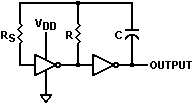
An oscillator comprised of two COS/MOS (COmplimentary-Symmetry Metal-Oxide-Semiconductor) inverters is illustrated in the schematic below. Also provided is a client-side JavaScript frequency calculator using the equation (eq. 1) in an application note published by RCA (ref. 1).
This oscillator exhibits excellent temperature stability and immunity to power supply variations, and is therefore a good choice for many applications. Applicable integrated circuit part numbers include Texas Instruments type CD4069UBE and ON Semiconductor type MC14069UBCPG. These parts contain six inverters, so it is possible to implement three separate oscillators per package. In practice, however, it is often desirable to follow the output of the second inverter with an additional one so that the oscillator is isolated from subsequent circuit loading and noise; therefore permitting two oscillators per package.
Note that these integrated circuits are comprised of "unbuffered" inverters, and that this oscillator is not recommended for implementation with "buffered" types.
The equation provides a useful prediction of oscillator frequency when the values of R (Timing Resistor), RS (Series Resistor) and C (Timing Capacitor) are within reasonable bounds. Generally, the equation provides the most accurate results when
1) the oscillator periods are relatively large compared to the propagation
and transition delays inherent within the integrated circuit.
2) C is relatively large compared to the inherent capacitances
within the integrated circuit and in the physical layout.
3) R is large enough to allow the first inverter's output to
swing close to the power supply rails.
4) RS is small enough to prevent a phase shift within
the oscillation feedback path due to the input capacitance of the first inverter,
but large enough to prevent the first inverter's input clamping diode from
loading the feedback network (recommended values between 2 and 10 times
R).
A comparison of actual and equation-calculated frequencies, using an ON Semiconductor type MC14069UBCPG integrated circuit and several different values, are tabulated in Table 1. The measured output was buffered by a third inverter in the same integrated circuit package, and taken at 25°C after a stabilizing period of 5 minutes. Note that the deviation is not singularly dependent on one variable. Also, a large deviation from the calculated frequency for certain sets of values does not necessarily disqualify the oscillator for use in a specific application.
VDD = 5.00V |
|||||||
RS ±1% |
R ±1% |
C ±1% |
RC |
Calculated Frequency |
Measured Frequency |
Deviation From |
Comment |
0.2 |
0.02 |
0.0001 |
2.0 × 10⁻⁶ |
198211 |
31812 |
-83.9 |
RS is large, contributing a phase shift that is appreciable for this frequency. |
0.02 |
0.002 |
0.001 |
2.0 × 10⁻⁶ |
198211 |
58130 |
-70.6 |
- |
0.02 |
0.002 |
0.01 |
2.0 × 10⁻⁵ |
19821 |
12028 |
-39.3 |
- |
0.00402 |
0.002 |
0.001 |
2.0 × 10⁻⁶ |
200432 |
136800 |
-31.7 |
- |
0.00402 |
0.002 |
0.01 |
2.0 × 10⁻⁵ |
20043 |
15985 |
-20.2 |
- |
0.00402 |
0.02 |
0.0001 |
2.0 × 10⁻⁶ |
215827 |
190066 |
-11.9 |
RS is intentionally made smaller than R, reducing the deviation, but possibly increasing temperature dependence. |
0.2 |
0.02 |
0.01 |
2.0 × 10⁻⁴ |
1982 |
2070 |
+4.4 |
Although RS is large, it contributes a phase shift that is negligible for this frequency. |
Schematic
Equations
![]() (eq. 1)
(eq. 1)
![]() (eq. 2)
(eq. 2)
![]() (eq. 3)
(eq. 3)
Variables
RS = Series Resistor
R = Timing Resistor
C = Timing Capacitor
VDD = Power Supply Voltage
VD = IC internal protection diode forward voltage
VT = Inverter threshold voltage
T = Period of oscillation
F = Frequency of oscillation
Calculator