 |
Four Phase Clock Generator
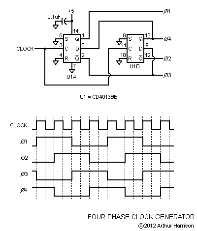
Here is an extremely useful circuit that may be applied as the timing core for any sequential digital process, using a single dual-flip-flop package, CMOS type CD4013BE. One of the four outputs (phase 1) provides a squarewave at one-quarter the clock input frequency. The phase 2 output provides a squarewave one clock cycle later, and phases 3 and 4 follow with a delay of two and three clock cycles, respectively. A supply of +5 volts is indicated, although the CD4013BE device may operate within a range of +3 to +15 volts. The maximum recommended clock rate is 3.5MHz for a +5 volt supply. For applications requiring higher speeds, the circuit is readily adaptable to a number of other flip flops such as those using the HCMOS or bipolar Schottky process.
My gratitude to Rick Hansen, who introduced me to this circuit and the essential tenets of digital logic in the 1980s.
|
November 30, 2012
Text and image ©2012 by Arthur Harrison
Back to the Circuit Library Index
Back to the Opening Page of Art's Theremin Page